This thread has been locked.

If you have a related question, please click the "Ask a related question" button in the top right corner. The newly created question will be automatically linked to this question.

ISO5852S: Different Internal Pull-up and Pull-down MOS Questions

Part Number: ISO5852S

Tool/software:

Hi Team,

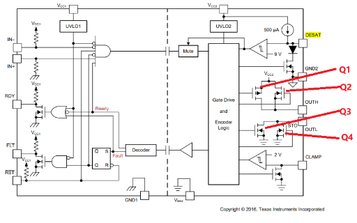
When customer using ISO5852s, he has following questions about the internal block diagram, could you please help provide your professional explanation here? Thanks in advance.

  1. Q2 is turned on when logic H, what is the role of Q1? When is it turned on?
  2. Q3 is turned on when normal logic L, and Q4 is turned on when overcurrent soft shutdown. What are the differences or drive circuit differences between Q3 and Q4?

BRs,

Francis

  • Hi Francis,

    Both Q1 and Q2 comprise the pull-up network. The NMOS quickly charges the gate to the threshold voltage, and the PMOS provides a higher resistance to control the turn-on gate drive current to the FET.

    2. Q3 is the normal strong turn-off. Q4 is only activated when DESAT is detected. In that case, Q3 is disabled, and Q4 applies a soft 400mA turn-off to the gate of the IGBT or FET.

    Best regards,

    Sean