Tool/software:
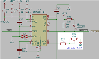
I developed a circuit incorporating the LM76202-Q1 as a circuit breaker. Its purpose is to act as a safety backup for an LED driver. If the LED driver was to fail leading to current consumption increasing above a safe limit, the LM76202-Q1 would disconnect the circuit and report a fault. I have made six of these circuits and they all work as intended.
The problem is that to achieve the desired circuit breaker threshold (110 mA - 115 mA) with the LM76202-Q1, I have to set the RILIM to a value of 83 kΩ ± 1 kΩ on these six boards. According to equation (5) in the datasheet, the RILIM for 113 mA current limit should be ~145 kΩ. This is very far away from what I found in my test boards.
I performed a multi-prong testing of the circuit to find the cause of the difference between the datasheet and actual RILIM values. I found absolutely no indication of any problem that could explain the difference. I am happy to share the test report privately.
I coming here with the hope to find the answer why the circuit, while working perfectly, requires a vastly different RILIM resistor value from the datasheet specification.