This thread has been locked.

If you have a related question, please click the "Ask a related question" button in the top right corner. The newly created question will be automatically linked to this question.

TPS546D24A: Reading wrong value for IOUT

Part Number: TPS546D24A

Tool/software:

Hello,

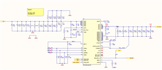
I encountered an issue during the reading of the IOUT using the PMBUS. My circuit has a 15V input voltage, and when I read the IOUT using PMBUS, I get something around 47A. When the input voltage is changed to 5V, the reading is 20 A, which is what I am expecting. Is the READ_IOUT somehow related to the input voltage? Follow the circuit below:

  • There is also a correction in the design, R27 is a 3.74k, not a 37.4k 

  • Hi Hugo,

    Are you using the TI Fusion GUI to measure READ_IOUT? Could it be a conversion error? You can use a PMBus decoder like this to make sure:
    5531.PMBUS_Value_Decoder.xlsx

    Another thing to look at is if you are connecting the AGND pin directly to the exposed pad under the IC. Not doing so will introduce current sense error and affect READ_IOUT accuracy.

    Thank you,
    Tomoya

  • Hi Tomoya,

    The design has the AGND connected to the exposed pad under the IC. If this were the issue, I should see the wrong current even for a smaller input voltage. The current reading on the PMBus is wrong only when the input voltage is increased to 15V. I am using the same firmware code that converts during a 5V input, so it's not the decoder or the calculation method. The only difference between the 15V and 5V tests is that during the 15V test, the TPS546 gets hotter (around 85°C), while at 5V, it is sitting at 56 °C.

  • Hi Hugo, 

    While it is expected to get hotter at higher VIN due to higher switching loss, etc., >30degC seems a bit much. 

    I checked on our EVM and don't see any error on READ_IOUT at higher VIN. 

    Please check your inductor current to ensure it is not getting saturated (at higher VIN, there will be a higher inductor ripple), as that could also mess up the current reading. 

    Thank you,
    Tomoya

  • Hi Tomoya,

    I will try to measure the current across the inductor to make sure it is not saturating. The current inductor has a saturation of 68 amps, and my load should pull no more than 20A (18W at 1.2V). I will send the test results soon.

  • Hi Hugo,

    That sounds good. Please let me know what you discover. Given the inductor's saturation rating of 68A, it is unlikely that the inductor is saturating. However, examining the inductor waveform will help us determine whether the reading from READ_IOUT is incorrect or if it reflects the actual current.

    Thank you,
    Tomoya

  • Hi Tomoya,

    This is the measurement I could get from the oscilloscope with a shunt after the inductor. Sorry for the measurements in voltage; I had to take quick measurements and didn't have time to set up the units, but I will walk you through it. 

    I currently have a shunt of 1 mOhms, so the oscilloscope shows a peak current of 59.2 mV, which translates to 59.2 A. Now, the behaviour of the current waveform does not look like what it should be for a buck converter.

  • Hi Hugo,

    I’m not entirely sure what’s going on here, and I agree that the waveform doesn't resemble the triangular shape we would expect. This might be due to a measurement issue, such as coupling from the SW node to the probe.

    If you have one, consider using a differential probe. Alternatively, you can use two probes across the 1 mΩ resistor and apply the math function on the oscilloscope to achieve a differential measurement.

    Could you also try out a different inductor to see if that helps with the READ_IOUT measurement? 

    Thank you,
    Tomoya

  • Hello Tomoya,

    I ordered different inductors to test them out. I have been reviewing several posts and datasheets for the TPS546D24A, and I haven't found a single paper that shows the expected current waveform for this device. Do you have any images of current sensing (waveform) in this chip done by TI?

  • Hi Hugo, 

    The TPS546D24A is a buck converter. In steady-state, the inductor current looks like a triangular wave with a DC offset. Since the device doesn’t have a skip-mode or PFM mode for light loads and operates synchronously, it will work in continuous conduction mode even at light loads.

    Thank you,
    Tomoya