This thread has been locked.

If you have a related question, please click the "Ask a related question" button in the top right corner. The newly created question will be automatically linked to this question.

TPS61094: Supercap not charging in on battery insertion

Part Number: TPS61094

Tool/software:

Hello TI an fellow EE,

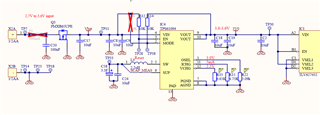
This is the power path for an iot device and while testing with multiple prototypes and batteries we have the problem that 70% of the time inserting my lithium LS14250 battery in the product the supercap is not being charged.

The idea behind this setup for EN and MODE is that on battery insertion the device is enabled and once Vout becomes high it goes to auto-buck/boost mode. The reason R14 is tied to Vout and not Vin is that with the battery removed Vin could drop to Vout -> device to bypass without reverse current flow, and then Vin could drop further and then the device gets disabled. Resulting in a user experience that removing the battery resets the device, instead of having to wait for possible a week for depleting the super-cap. I am still testing this. 

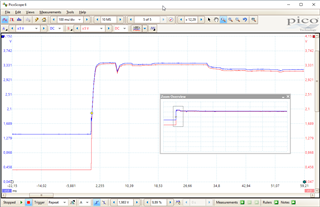
In normal operation, both EN and MODE should be high and with a fresh battery the supercap should be charging. This is however not the case. Lithium thionyl can be a bit lazy if they have been on stock. That is probably why with my bench supply at 3,6V i have seen this occur only once, thinking it was a manufacturing defect and continued testing the other prototype. If you wait for a few hours the supercap usually ends up at around 0,3V while not charging. Waiting 24h does not increase further. Pulling EN low (with a button to gnd on TP28) usually fixed the problem. sometimes you needed to press it multiple times. Once it started charging everything worked as expected.

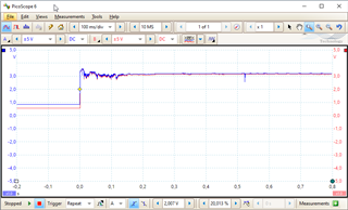
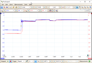
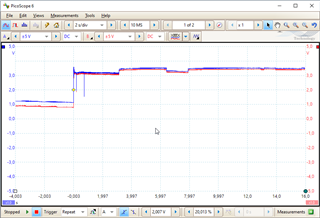
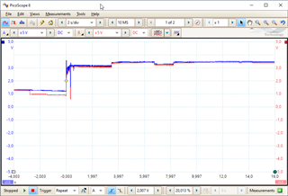
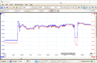
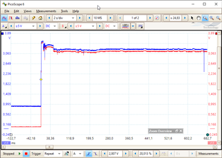
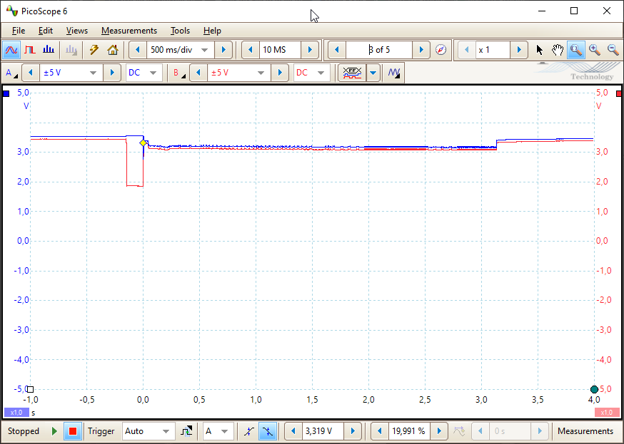
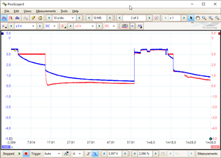
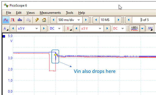
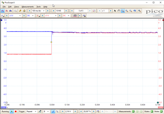
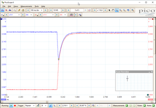
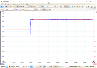
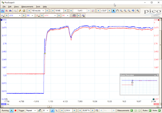
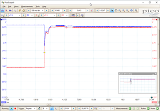
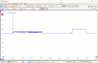
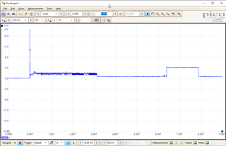
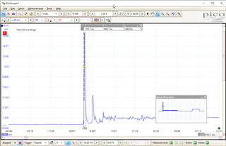
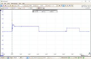
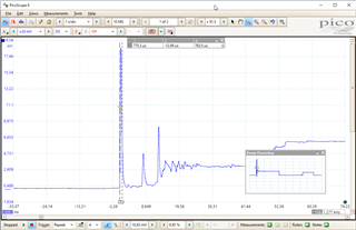
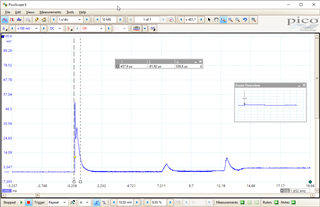
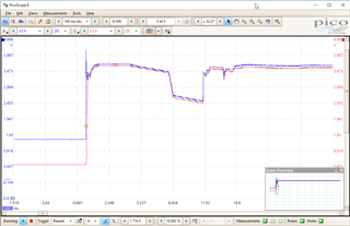
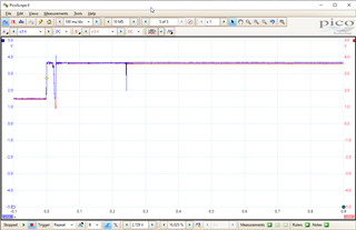
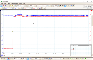
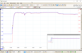
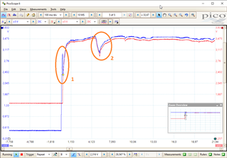
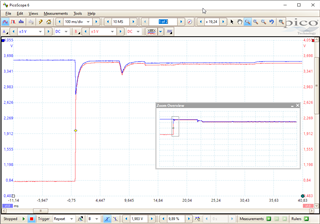
I tried to reproduce the problem and I can do that when a 10k series resistor is inserted series with the PSU. This is too big of a series resistor to sustain the current of the product (30mA peak, 6uA sleep) and the charge current of the supercap. Once i short the 10k resistor, Vout rises to Vin, but the supercap does not start charging, even while i expect it to do so. After a lot of testing i found out toggling MODE low, forces the chip to charge and even after releasing the button, it continues charging as it should. Of course the internal resistance of the battery is much lower, but this worked for reproducing the problem. 

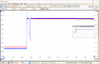
I have the feeling the chip latches in some weird state and misses the trigger it can start charging the supercap if the input voltage is sufficiently high. If i slowly turn on the input voltage charging starts when above the 3,0V setting of OSEL as expected. 

For now i think the fix/patch is forcing MODE low with a transistor controlled by the microcontroller until the supercap is charged to about 0.85V (Vsup_uvl).

I measure the supercap voltage with the device microcontroller with this circuit

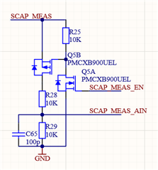
probably not of interest, but for completeness you never know. The microcontroller runs at 1,8V so i need a low power way to bring it down. 

I really would like to prevent coming into this state and even more prefer to exit it without adding logic, software and another revision. But the most important part is understanding what is happening and knowing the fix is a solid solution. All idea's are welcome :)

Thanks in advance,

Ruud

  • Hi Ruud,

    Let me check and reply to you today. 

    Regards

    Lei

  • Hi Ruud,

    we have the problem that 70% of the time inserting my lithium LS14250 battery in the product the supercap is not being charged.

    For this verification, is the same one battery used? What's the voltage of the used battery?

    Is the battery inserted by hand? If so, I think there may be a big Vin ripples. If available, you may capture the voltage waveforms by a oscilloscope.

    Could you try a quick experiment as below:

    1. Set the EN = low and mode = high, to disable the device;
    2. Insert a fresh battery, make sure that the battery voltage is high than the Vout target (3V);
    3. Pull the EN high to make the device in auto buck or boost mode.

    Regards

    Lei

  • Hello Lei Zhong,

    Thanks for your quick reply.

    For testing i use the same battery continuously, but for production we use new ones, which could have been on stock for serval months. 


    Blue input at VIN (TP11) and VOUT (TP30).
    When i measure the battery before insertion with my multimeter it is 3.67V
    When inserting the scope measures the first peaks at 3.65V, but the deeper drops in the first 150ms are 2,7V. After 600ms it is 3.05V
    Supercap is around 0,5V.


    In the above capture it started charging the supercap succesfully

    In this one it did not

    This one was succesfull

    Zoomed in on the battery insertion, wee see some nice contact bouncing. This is off course to be expected for a battery product i guess. 
    Also interesting to see that the voltage drops quite significant in the beginning. These are all the processors booting. Current consumption here is probably a bit higher. I might be able to do some software optimization here too, i could probably shave off 3 seconds, not sure. 

    None the less i expect the chip to go to buck mode once the voltage has rissen sufficiently. At 4 seconds it is 3,35V


    This one also not succesfull. 

    Here i press the enable button to pull enable down. The device goes to true shutdown mode, and you see the output drop instantly to 1,8V, the voltage of the next converter and subsystem. This time pushing the enable did not start the charging sequence. sometimes it does it instantly, sometimes you need to try 10 times. 

    I also made a button to ground on the mode pin. Pressing this always fixed it instantly. This is probably a hint that the main problem is not only in insertion, but the bigger load on startup and floating around the 3V which is the OSEL setting. 

    Nonetheless i expect it to go to supercap charging after those initial 3 seconds of bigger load. 

    If there is more to test or measure Let me know. 

    Bonus measurement:


    Input and output, when i remove the battery. You see the input voltage slowly drop, in about 15 seconds to 1.8V (scope in 1/10 mode, but we don't know if it also drops if we don't attach the scope). It does not drop further so the tps61094 remains enabled and active in boost mode. Next event i press the mode button forcing the chip in buck mode, immediately dropping the output voltage. Next event i re-insert the battery. The supercap is not empty here so this helps in startup i guess, supercap is charging. This time i press the button really short but still enough to drop the output voltage to 1.4V, which should be sufficient to disable the system. It is a good thing that the input drops far beyond the output though, so probably i can measure and detect battery removal. 

    So maybe controlling the mode pin with the MCU can also have an advantage here. 

  • Hi Ruud,

    Thank you for reaching out. Expert for this part is OoO today. Please expect a late reply. Thanks.

    Regards,

    Mulin

  • Hi Ruud,

    Sorry for the late response.

    I think the issue is related with the contact bouncing when the battery is inserted.

    In your application, is it possible to pull the EN down, insert the battery, waiting for the Vin voltage is stable, then pull the EN to high?

    Please note that when you try to pull the EN to high, will the TPS61094 load be very big when the Vout reaches the target? If so the instant input current is also big and make the voltage at the VIN pin drops.

    I'm asking because I watched Vin drops in the following picture you attached when EN goes to high.

    As a short summary, the ideal sequence will be as below:

    1. Disconnect all the load at the TPS61094
    2. Pull the EN to low
    3. Insert the battery
    4. Waiting for the Vbat to be stable
    5. Pull the EN to high
    6. After the Vout reaches the target, connect the load

    If the above sequence works for your circuits, please have a try.

    Regards

    Lei

  • Hello Lei,

    It is really hard for me to disconnect the output, as it is distributed on an inner layer connected with via's under the output capacitor. I can start removing subsystems if needed, but i feel like if it works without powering my board, we still did not learn anything valid. So i try to get valuable data without removing the output. 

    Battery insertion with enable low. Some voltage gets to the output. That should not be possible to leak through my system, but i have to remove everything for that to be sure. Also it is is not an issue, there normally is no state with the TPS disabled.

    This did not increase the chance of it to get charging. (tried 20 times, 0 started to charge) (press on mode pin to pull it low, release it, and it starts and keeps charging, works every time). If i button bash it (press it multiple times in fast succession) i can get it to work with the enable, otherwise not. If the supercap is above 0.85V it keeps working, But i test with it <0,6V.


    Zoomed in on the enable event. 

    The input voltage drops to about 2.5V. All the capacitors on the pcb add up 


    I removed the wifi subsystem, which is connected to the 3V0 Net via a loadswitch (TCK108AG). I removed the load switch to make sure that even without the microcontroller powered the system does not contribute to the load.


    The measurement still looks the same. So the output capacitors of the TPS itself are the main contributors.

    But now every time i hold enable while inserting the battery, and then let it go, it starts. tried 20 times or so. Next tried inserting the battery without holding the enable button to pull it low. I re-tested the above measurements with another prototype, to be sure i tested it well. 


    above a battery insertion which failed to start the supercap charging. 


    above is zoomed in of the above, of a failed try. Pressing enable did start it this time. see below.


    Next i measured the startup current, without wifi. Measured with the EEVblog uCurrent set to 0,1mA/1mV measured through a 1R shunt. Scope connected to the output.

    not charging 4.7mA


    does charge 8.4mA

    (The current in these prototypes is debug firmware so low power is not correct). The first 3 seconds is around 20mA. then 8, and from 6,5 to 8s around 38mA.

    Current exceeds the 200mA scale and is about 100us wide.

    Without wifi it starts about 9 out of 10 times when inserting the battery. Big improvement, still unacceptable :).

    Next i test with my prototype with wifi. 


    Initial current block rises to 50mA, with the smaller bump before that of 65mA for 180ms.

    The inial peaks are also wider. 
    Re-measured with different scale

    up to 510mA when inserting the battery. Which is surprising given we have 30uF on the input. 

    Conclusion up till now: reducing power consumption improves the odds greatly, though it does not fix the problem. Holding the enable button when inserting the battery makes it worse with wifi subsystem, and better without. In both cases the load is nowhere near the limits of the TPS61094.

    Are the values of OSEL, ICHG and VCHG resampled on a MODE pin change? maybe it reads the wrong setting when the input voltages are not yet stable due to startup? A wrong configuration could lead to not charging? toggling EN only fixes it if the following enable event does not result in a violent swinging of Vout and Vin? That is maybe why mode does fix it reliable, the output and input remain steady over that event. Or something else, just thinking out loud :).

    Ruud

  • As a bonus i changed the battery to the lab supply. configured to 3.55V and to simulate the insertion, i insertion the banana plug. 


    Some violent swinging, it started to charge however.

    I was going to say it works every time, but i got it to fail


    And another fail

    pressing enable fixed it.

    (tested the part with wifi)

    I feel like this part is designed for exactly this use case so i think it should handle these events without getting in a state that needs intervention.

    ruud

  • Hi Ruud,

    Let me check and reply to you by tomorrow.

    Regards

    Lei

  • Hi Ruud,

    Are the values of OSEL, ICHG and VCHG resampled on a MODE pin change?

    These values of the OSEL, ICHG and VCHG are sensed and locked at the status from shutdown to startup. Once locked, they won't be changed in other working status.

    maybe it reads the wrong setting when the input voltages are not yet stable due to startup?

    There should be no this kind of concerns.

    A wrong configuration could lead to not charging?

    Is it possible to avoid the Vin drop below Vout target when the supercap voltage is still lower than SUP UVLO?

    toggling EN only fixes it if the following enable event does not result in a violent swinging of Vout and Vin?

    In previous suggestions, the purpose of pulling EN to high after the battery is inserted is to avoid the Vin drop caused by the contact bouncing. Well, in your experiment, even so the Vin may still drop, which should be caused by the TPS61094 load. 

    So, again, are there any ways to avoid the Vin drop below Vout target when the supercap voltage is still lower than SUP UVLO? For example, increase the Cin capacitance?

    Regards

    Lei

  • Hello Lei,

    I ordered some AVX Low leakage Tantalum TRJB476K006R0500 (47uF 6,3V 500mR) which is the biggest i might be able to squeeze in. 

    It will take a day or maybe two to get here and test.

    This battery type has a large internal resistance, hence also the function of the supercap :). Maybe some slew-rate control or soft-start on the Vin to Vout mosfet could improve this behavior? :)


    Can you maybe tell me if the fix with toggling the MODE pin low is a reliable solution?

    Thanks also for your other insights, then i think we can conclude that given the mode seems to fix it, the configuration is correctly sampled.

    Ruud

  • Hi Ruud,

    Maybe some slew-rate control or soft-start on the Vin to Vout mosfet could improve this behavior? :)

    L;eThat should be good trying.

    To minimum the voltage drop during the start up, another trying is to chose a supercap with smaller ESR.

    Can you maybe tell me if the fix with toggling the MODE pin low is a reliable solution?

    If it's convenient, please also have a try.

    Actually, the purpose of all the trying is the same: avoid the Vin drop below Vout target when the supercap voltage is still lower than SUP UVLO in auto buck and boost mode.

    Regards

    Lei

  • Hello Lei,

    I was a few days out of office but here we are again :)


    succes


    and fail on the 7th try. 


    These look very similar, i can't tell why the 1st time has succes and the above fails. When compared to before the extra input capacitor you can see that the input voltage spike on insertion is nearly gone and 2 the voltage dip is a little less this time, but very little. 


    inserting while enable is low and then releasing enable, we get the above measurement. It improved, so did the outcome of the test. First the input voltage dipped to about 2,2 - 2,5V now that is 2,75 - 3V. I tested about 30 times and every release of the enable resulted in a succesfull start of the supercap charging. 

    In the end it has to be reliable with manual battery insertion. And controlling enable  would need a power supervisor or something simular in analog. I think a simple RC with the contact bounce won't be reliable in all situations. Also a chip like this should not need an external power supervisor on the enable. 

    By toggling the mode pin, i can assure that Vin is above Vout (OSEL) when making MODE high. If i do that when the supercap is sufficiently above it's UVLO can we then conclude this is a reliable solution? I think so but i also would like your confirmation on that. 

    Then also i don't add the tantalum capacitor as potentially adds conflict minerals to my product, while increasing the BOM and the current leakage. 

    I think it is not needed because once there is sufficient charge in the supercap the TPS61094 does not rely solely on the battery anymore. 

    Kind regards,

    Ruud

  • Hi Rudd,

    Sorry I may have a late response this week, but I'll make sure to provide feedback by this Friday.

    Regards

    Lei

  • Hi Rudd,

    On your latest attached pictures, it seems that the Vin drop was caused by a short and big load pulse. Can this kind load pulse can be active after the supercap voltage above the SUP UVLO?

    Go back to your question:

    By toggling the mode pin, i can assure that Vin is above Vout (OSEL) when making MODE high. If i do that when the supercap is sufficiently above it's UVLO can we then conclude this is a reliable solution?

    "Toggling the MODE pin" is a little ambiguous. If you mean that the MODE pin is low at the initial status, after the Vin is above Vout (OSEL), then pull the MODE pin to high. If so it should be a reliable solution.

    Just let me know if you see any concerns.

    Regards

    Lei

  • Hello Lei,

    I pushed out a revision of the pcb with a control over the MODE pin. By toggling i mean what you say, at MCU startup which controls the MODE pin, MODE pin is made low. The MCU also reads the supercap voltage. When the supercap voltage is above  VSUP_UVLO rising + some margin, i release the MODE pin. this ensures Vin does not drop above Vout. The MCU halts power hungry functions until the supercap is sufficiently charged. 

    I think that should mitigate our problem.

    Ruud

  • Hi Ruud,

    I think so. Thanks for your feedback.

    Just let me know if you have new findings or see concerns.

    Regards

    Lei