


Tool/software:
Hi teams:
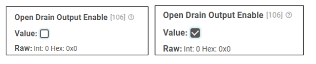
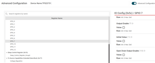
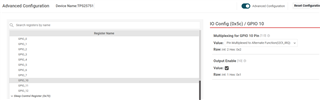
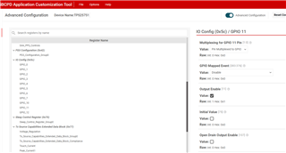
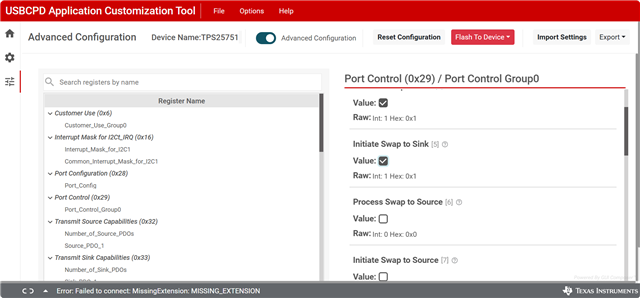
this is what I did to modify IO Config register (0x5c) in GUI advanced mode
but I found that the bit 106 remains same "RAW:Int:0 Hex:0x0" when I checked on the "Open Drain Output Enable" value.
shouldn't this bit [106] be "RAW:Int:1 Hex:0x1" when "Open Drain Output Enable" value is checked ?
Best Regards!
Iris


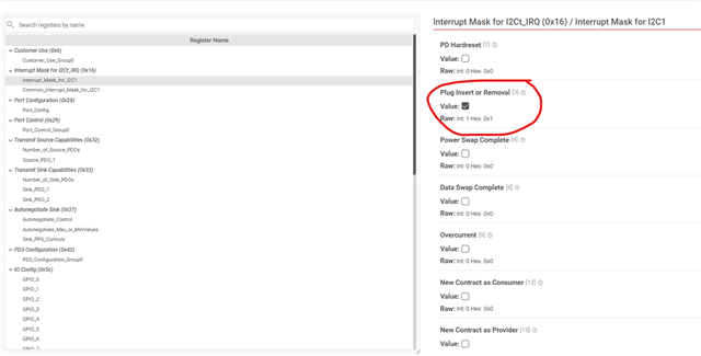


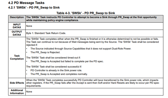 From the TRM.