Tool/software:
Hello,
I am designing a 6S2P UPS using the BQ25750 to charge the batteries and perform power path management for the system rail as well. Within the design I want to integrate one of DALY's smart, active balancing BMSs. I have been trying to workout how to wire the system, considering that their BMS is wired in series with the cells (the load current passes through the cells and the BMS for monitoring), as shown in the attached wiring diagram .
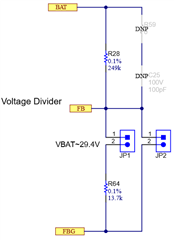
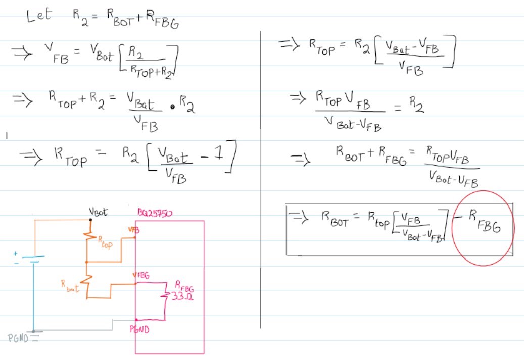
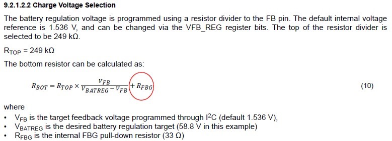
Looking at the wiring schematics of the BQ25750 in the datasheet, I should use the FB and FBG terminals for accurate battery voltage monitoring, and as mentioned in the datasheet the FBG pin is grounded to PGND during charging. Considering the inclusion of the BMS as highlighted in the wiring, how should I connect the BQ25750 to ensure it senses the correct voltage of the cells? If I connect B- to FBG of the IC, during charging FBG would be shorted to PGND, effectively shorting out the BMS, since P- of the BMS shall be connected to PGND.
On the other hand if I connect FBG to the P- terminal of the BMS, or effectively to PGND, the voltage sensed by the IC would not accurately represent the battery voltage as it would also include the voltage drop across the BMS. In furtherance, the datasheet makes reference to PGND and AGND in Figure 9-1, but without specifics; just that AGND is connected to the sensing terminals. Could this be part of the solution?
On a final note, will the inclusion of this BMS interfere somehow with the BQ25750's ability to sense VAC abnormalities and to directly switch the load to battery power seamlessly. The UPS is meant to supply a critical load and switching shall be almost instantaneous (max 1ms of 10% droop is allowed - System rail shall be 24V and the maximum load would 3A)
Your suggestions for solutions to this matter would be much appreciated.
Regards,
Mahmood