Other Parts Discussed in Thread: , TPS25762-Q1, TPS25772-Q1, TPS55289-Q1, TPS55288-Q1, TPS25763-Q1, TPS26744E-Q1, LM251772-Q1, LM72880-Q1
Tool/software:
Hello,
I want to be able to design a USB PD PPS-capable charger, so I need a source controller chip which can do PPS not just regular USB-PD.
I want it to be either an all-in-one solution or to be compatible with DC-DC converter ICs... just not AC-DC flyback but rather regular buck or buck-boost.
Most importantly that I don't need it to require software or coding or I2C commands...etc.
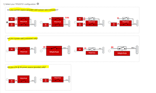
I saw TPS25751 but could not understand how it can fit my needs. I am ok with it having I2C but want to be able to use it in default settings without the need to reprogram it.
can you help with this?
thanks