This thread has been locked.

If you have a related question, please click the "Ask a related question" button in the top right corner. The newly created question will be automatically linked to this question.

TPS65987DDK: Help with configuring for Alt Mode

Part Number: TPS65987DDK
Other Parts Discussed in Thread: TPD8S300, TPS65987

Tool/software:

Hello e2e, 

I am working on finding the correct configuration for a device that should be alt mode capable. Forgive me, I am a beginner with the PD protocol. The device should primarily look to be a sink in the power context (UFP) and a source in the data/alt mode context (DFP_D). We are using the GPIO configuration. So far, we have been able to see the device sink, although it only negotiates for 5V even though it has been configured with 4 sink PDO's up to 20V. Our protocol analyzer shows a negotiation occur with several messages going back and forth. When we connect a display through an externally powered usb hub no messages appear to be going across. Another concern is that the same image when programmed onto one of the EVM's, appears to be functioning correctly on the EVM. 

Please let me know what data you would like me to share. I can send the schematic in a private message. 

Any assistance you can provide would be invaluable, thank you.

  • I should specify, I have configured the "display port capabilities" section and the "i/o config" sections with the options shown in section 3.1 of document slva844b

  • Hi Sardonic,

    The TPS65987DDK is NRND(Not Recommended for New Designs). It will not be able to support passing compliance for the active versions of the PD spec, and will have limited support going forwards. (No new features, limited bug fixes).

    If you are ok with this, we can continue supporting you, but just keep in mind some of the limitations.

    What protocol analyzer do you use? Can you send the logs and screenshots for the working and non-working cases?

    Please share the pjt file used to configure the device.

    Which GUI version are you using?

    It sounds like there are a couple issues.

    1. 5-V only sinking
    2. DP not working

    Can you share a block diagram of how you are testing? You have your device, a usb hub, and a monitor?

    What is connected when you do see messaging?

    Thanks and Regards,

    Chris

  • Hi Chris, 

    Yes we are aware and okay with the part being NRND. 

    I am using the cypress/infineon ez-pd (cy4500 I believe). I can capture some logs for you tomorrow if that's okay. 

     I have tried a few different configurations, but here is one of the more recent project files. 

    altmodegpio.pjt

    I am using GUI version 6.1.4

    The block you described is correct, however in that case there were no messages seen (connecting to the dock). When I saw messages back and forth though that was by connecting the device directly to a laptop or wall charger.

    Thank you very much, I will collect some more data to share with you tomorrow.  

  • Hi Sardonic,

    I am using the cypress/infineon ez-pd (cy4500 I believe). I can capture some logs for you tomorrow if that's okay. 

    Yeah, that works. I have the software for this decoder, so the raw log files should be fine, no need for the screenshots.

    Thanks for the responses to the questions, everything seems fine from there. I'll wait for the PD logs.

    Thanks and Regards,

    Chris

  • Good morning Christopher, 

    I have collected a few logs. 

    altmodegpio1: board unpowered, first plug into a samsung wall charger, then a dell dock, then a laptop. in this case the board should be able to be fully powered from a charger. 12V3A instead I am seeing it source about 5V with miniscule load. 

    altmodegpio2: board powered. same steps as above. first plugged into wall charger, then dock, then laptop. 

    next I attempted to connect to a display. first, I attempted a c2g hdmi to usb c adapter which was connected to external power, in this case I see no messages at all. 

    altmodegpio3 and 4 represent connecting via a different dongle, it is unbranded but it is one of those small silver ones that have an hdmi port at one end, it was also connected to external power. In this case you will see many messages however according to my ammeter it is constantly switching back and forth between sourcing and sinking. In altmodegpio3 at first the display was not connected and I connected it at line 36. in altmodegpio4 the display was connected from the start. 

    I hope my explanation is not confusing!

  • it seems the forum does not like the files I am trying to upload. I have sent you a friend request. 

  • Hi Sardonic,

    Can you try just dragging the file from file explorer directly into the reply box? You should be able to easily share these files here.

    Like this:

    https://e2e.ti.com/cfs-file/__key/communityserver-discussions-components-files/196/example.ccgx3

    It initially appears in a different icon, but resolves itself when the message is sent.

    Thanks and Regards,

    Chris

  • yes, that is what I am attempting. the text box greys out and says "uploading "filename"" but when the grey disappears there is no icon. it seems to be okay with a zip file so I have attached that here. sorry about that, let me know if you need a different archive format. 

    altmodegpiologs.zip

  • Hi Sardonic,

    Interesting, i've never seen that issue before.

    The zip file works well! I was able to download and opened one of the logs.

    Please give me a couple days to review the logs and provide feedback.

    Thanks and Regards,

    Chris

  • No problem Christopher, thank you. 

    In the meanwhile, I am wondering if there is any utility which can unpack a pre-existing image? alternatively, I have had trouble using the "import settings from device" feature in the application customization tool. It claims success when instructed to load into global device settings tab, but I do not have any global device settings tab I have a tab which says "general settings" and another which says "device 1" neither of which seems to be updated. When I select "device 1, port 1" option I get a failure. 

  • Hi Sardonic,

    Some old images may not be able to be imported correctly into the tool.

    Import settings from device is typically a feature reserved for the EVMs, are you testing on an EVM here? How is the GUI connecting to the device in order to read settings?

    Thanks and Regards,

    Chris

  • Sardonic,

    I accepted your friend request. Could you send me your schematics over private message? For high voltage sinking, the pjt looks ok, so I have concerns you are not loading the image to the PD controller properly on boot.

    Do you have access to the I2C1 or I2C2 lines, and a tool to read registers from the PD controller? If so, can you read the Customer use, Mode, Boot Flags, and Port Control registers after flashing the ...tiv1.pjt image to your system?

    What sink PDOs do you want to support? The Transmit Sink Capabilities register settings may be causing issues.


    Logs 1 and 2 show no PD communication. Could you send a link to the device you are connecting to the port?

    Logs 3 and 4 are confusing as the request message does not seem to match the sink capabilities you have set in the "altmodegpio" pjt you shared. In addition, you have power role swaps and data role swaps disabled in your project so I'm not sure how the PR_Swap is happening.

    Are all the logs taken from your custom board and not from the EVM?

    I made some modifications to the sink pdos in the Transmit Sink Caps register and to some DR swap functionality in the Port Control Register.altmodegpio_tiv1.pjt

    Thanks and Regards,

    Chris

  • Yes, I am attempting to read from an EVM. One of my colleagues was successfully able to get display capabilities on the DDK evm but he cannot recall the configuration he used. However, when we just read the image off the evm with the aardvark and load it onto our board it behaves differently from the evm. I have attempted this with the aardvark adapter and also the tiva adapter. aardvark adapter always fails, tiva is able to give me the false success. 

    thanks

  • Chris, 
    I will send that right away. 
    It looks like we did route out I2C1 to our programming header but not I2C2. I will look into reading the registers it may take me a little bit of time, we are loading directly to the spi flash with the aardvark. 
    For sink capabilities, our device is battery powered, power draw with maximum load is 12V at around 3A. We would like the board to be able to sink enough power to stay on as well as charge the battery. What I have observed is if we connect our battery and also a charger, then disconnect the battery the board will turn off briefly before sinking enough current at 5V to turn back on (this is without the main load on the board), but if we turn the board off with our switch and try to turn it back on it is not able to pull enough power to turn back on from off state. 

    Yes, all the logs were taken from our board not the EVM. In logs 1 and 2 the devices I attached, in this order, are 
    Samsung adaptive fast charger model ep-ta20jbe. 
    Dell dock model wd19tb (I have definitely seen communication with this dock on the evm)
    dell laptop precision series. 

    Thank you again!

  • Thanks,

    Still reviewing and will get back to you by early next week.

    Thanks and Regards,

    Chris

  • Hi Chris, 
    I just wanted to flag for you that I sent you a message with the results of some hardware mods we performed. I've referenced the schematic. Thank you. 

  • Thanks for letting me know.

    I'll get feedback to you tomorrow.

    Thanks and Regards,

    Chris

  • Hi Layanne,

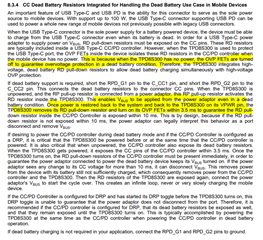
    Regarding the sinking failing when the wall adapter is connected, I think your EE is correct about the TPD8S300 VPWR source.

    When used with the TPS65987, the TPD8S300 should be powered by LDO3V3 of the TPS65987.

    How we expect the system to power up in dead battery is as follows.

    Source connected to port, TPD exposes RD resistors and Source will provide 5V on VBUS.

    TPD is in an unpowered state, so CC line switches are open.

    VBUS passes to TPS65987, which then generates LDO3V3 from VBUS.

    TPD device is then powered on from LDO3V3, closing the CC line switches

    TPS65987 CC lines are now exposed to the port and PD communication can happen.

    Please try powering the TPS8s300 VPWR from LDO3V3 instead of the P3V3 rail.

    It seems like you have found a solution for the display issues? Are there still questions there? If the EVM is working with the DP signal, I'm a little surprised you need to short HPD to CTL1 to get it to work.

    Thanks and Regards,

    Chris

  • Hi Christopher, 

    Thank you for your reply. I would like to clarify that we are getting VBUS power, the problem is that it is only negotiating 5V and this seems to be affecting it's ability to turn on from dead battery. We power the PD controller andTPD8S300 from the same 3v3 so they are powered at the same time and should support dead battery mode.

    In regards to the display issues, is tying HPD to CTL1 a permanent solution? We would like to understand why HPD is not being brought up when it should.

    Thank you for all your feedback, I have shared some additional notes in the DM. 

    Best,

  • Hi Layanne,

    When you see the sink failing, is P3V3 for VPWR of the TPD8S300 being powered? Can you confirm this? If P3V3 comes up in a dead battery condition you may be fine.

    Do you see a voltage on the system side of the CC line switch of the TPD8S300?

    If we can confirm that the TPD device is powered and passing the CC lines through.

    I added another comment about this related to your schematic in DM.


    Let me look into the display issues more. The GPIOs should work and you should not need to short HPD to the GPIO pin, but there could potentially be an issue there.

    Thanks and Regards,

    Chris

  • Our problem is not just when the battery is dead. When the battery is full as well. When the battery is full the unit can supply power to the PD controller and TPD8S300 .When we connect PD source, why is it sinking only 5v even though the setting is to sink 12 or 15v? On the battery charger datasheet, it says if battery and PD source (vbus) are connected , VBus takes priority. I will share charger details in DM

  • Regarding the display, our display port interface is USBC PD and not Display port or HDMI which have HPD signals.

  • Hi Layanne,

    Regarding the display, our display port interface is USBC PD and not Display port or HDMI which have HPD signals.

    USBC PD DP alt mode tunnels the HPD signal. Depending on the IC used for DP(i.e. the TUSB part or a DP scalar) sometimes a physical HPD signal is required or the ic can support a "virtual HPD" through I2C or another protocol.

    When we connect PD source, why is it sinking only 5v even though the setting is to sink 12 or 15v? On the battery charger datasheet, it says if battery and PD source (vbus) are connected , VBus takes priority. I will share charger details in DM

    This one is a little weird, your configuration looks fine regarding sinking, but I'll test your image on an EVM to see if I can replicate the behavior today.

    Thanks and Regards,

    Chris

  • Hi Layanne,

    See PMs, I couldn't get your pjt to sink hv contracts and ended up making a fresh pjt and copying settings over. I see it working for sinking on my end now.

    Please test and let me know the results.

    Thanks and Regards,

    Chris