This thread has been locked.

If you have a related question, please click the "Ask a related question" button in the top right corner. The newly created question will be automatically linked to this question.

LM5156: LM5156

Part Number: LM5156
Other Parts Discussed in Thread: CSD19532Q5B

Tool/software:

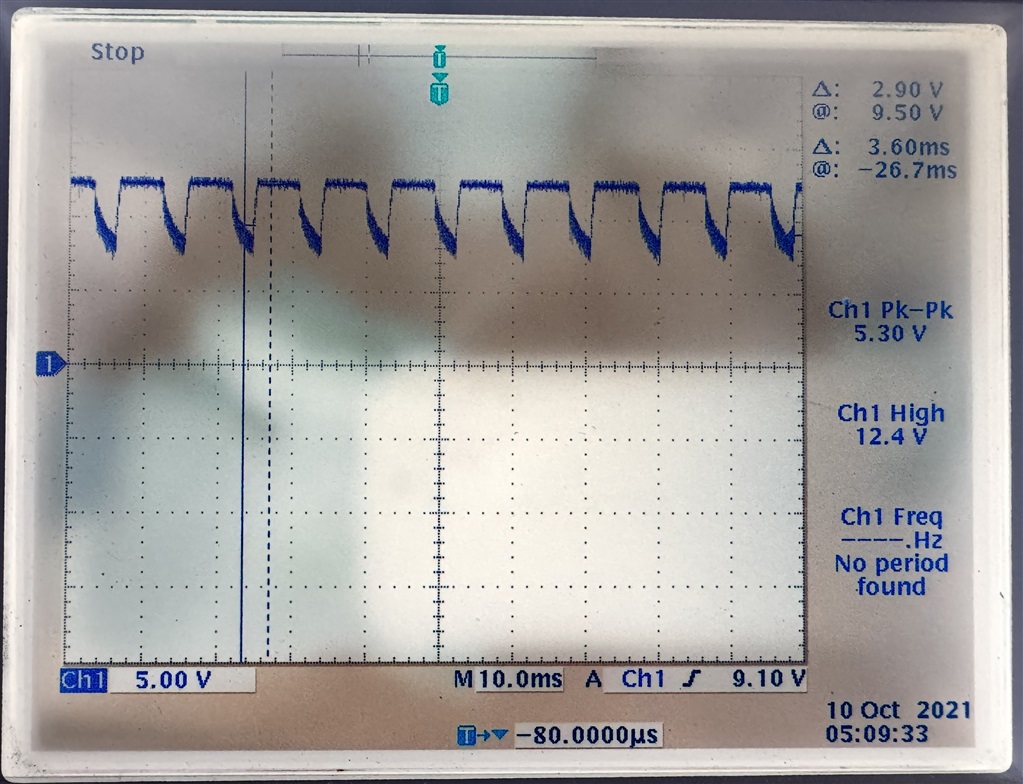
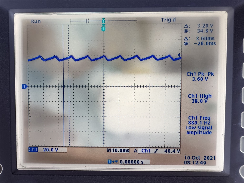
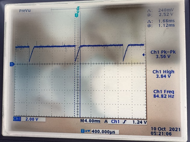
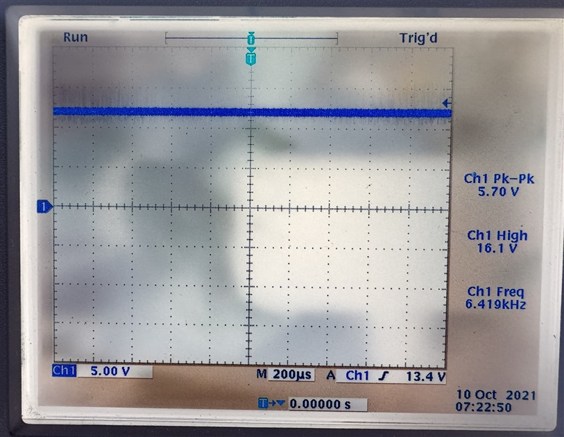
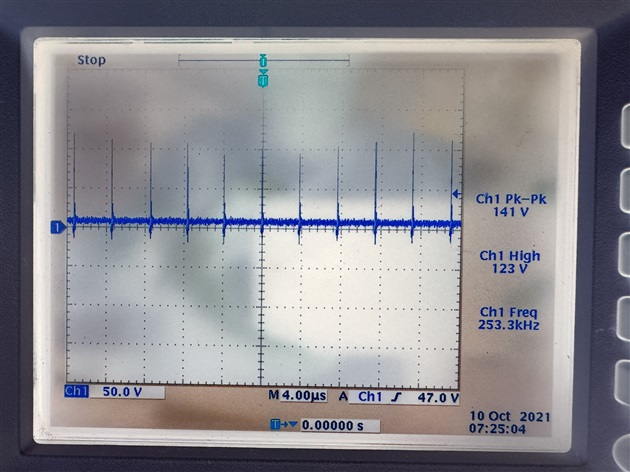
We have tested the LM5156 isolated booster circuit. It shows abnormal operated. The input current is much higher even with no load at the output. D45 output diode temperature abnormal with > 150degC. Do you have any ideas of the abnormal symptoms, do you have any suggestions of debugging? Please provide the comments that we can fine tune the circuit.
  • Hi Steven,

    Thanks for reaching out. 

    The Vout should be 54V, right? But it only reaches 39V, even in no load condition.

    Can you please share some scopeshots of Vin, Vout, switchnode and COMP pin please?

    Best regards

    Moritz

  • Hi Moritz,

    Thanks for the quick response.

    The designed circuit Vout should be 54V, but it is now only reaches ~39V even in no load condition. Vin is 12V 1.8A now.

    Please check with the following scopeshots of  Vin, Vout, SWP and COMP.

    Vin:

    Vin

    Vout:

    SWP:

    COMP:

    Thanks,

    Steven

  • Hi Steven,  

    The response will be delay due to public holiday, please expect feedback on Friday. Thanks. 

  • Hi Steven,

    Our experts for this device is out of office until Monday. We kindly ask for your patience and understanding. 

    Please expect a response early next week.

    Best regards,

    Mounika

  • Hi Steven, 

    It would be great to have the measurments all measured at once on the same plot.

    But anyway, i can see that the input voltage is dropping. This should not happen. Please make sure the power supply can keep the input stable first.

    Best regards

    Moritz

  • Hi Moritz,

    The Power Supply we use are stable 6A power source. The output becomes 0V by today's measurement. The following are the measured scopeshots. Do you have any idea that the LM5156 is malfunction? Any datas need us to provide to speed up the trobleshoot? Please advise.

    Vin:


    Vout:

    SWP:

    COMP:


    Thanks,

    Steven

  • Hi Steven, 

    Did you change something on the circuit so that it does not work anymore now?

    From the actual measurements i can see that the device is not really switching now. 

    Can you please fill out the quickstart calculator: https://www.ti.com/tool/download/SNVC240 

    Also please shre the datasheet of the transformer and the used FET.

    Do you have 4 probes for your oscilloscope? For further debugging the waveforms should be measuredd at the same time.

    If you are able to bring the device up again, please make sure the Vin is stable and provide the same measurements like above in one scopeshot.

    Best regards

    Moritz

  • Hi Moritz,

    The Mosfet Q45 is Texas Instruments CSD19532Q5B, the transformer is APPS AE-SFD20047. Datasheet as attached.

    1682.AE-SFD20047.pdfcsd19532q5b.pdf

    Thanks,

    Steven

  • Hi Steven, 

    Thanks for the files. Were you able to bring the flyback back up again? 

    If not, you can also check the CS pin to see if overcurrentlimit is hit. Also check if the device is enabled (Voltage at UVLO pin above the threshold)

    Best regards

    Moritz

  • Hi Moritz,

    Thanks for the comment.

    It is unable to bring the flyback back up now. Input 12V 0.31A without output voltage. CS pin 0V, UVLO pin 2.06V. 

    The scopeshots of CS and UVLO pin are shown for your reference.

    CS:

    UVLO:

    Thanks,

    Steven

  • Hi Steven,

    It is difficult to debug this from the outside, it would be important to bring the flyback up again somehow..

    As it already switched before, could you try to replace the IC as well as the MOSFET?

    Best regards

    Moritz

  • Hi Moritz,

    We have already tested 3pcs board with the same symptoms now. Do it possible ship the board to you for further debug?

    Thanks,

    steven

  • Hi Steven, 

    Unfortunately we do not ahve bandwidh to support a debugging on our side.

    It would be good if you could bring up the board again somehow. Then i can support the debugging step by step.

    Are the other boards also not switching at all? 

    Best regards

    Moritz

  • Hi Moritz,

    Yes, tried other boards also not switching. The output voltage is 0V. Any cause will induce the switching failure. Please advise.

    Thanks,

    Steven

  • Hi Steven,

    It is strange, because before you had a board switching. 

    do you have 4 probes for your scope? I would like to see Bias pin, VCC pin, gate pin and COMP pin at once.

    Best regards

    Moritz

  • Hi Moritz,

    The Bia pin, VCC pin, gate pin and COMP pin capture as shown below.

    We have found the problem why it is switching failure. To stable the input source we have enlarge the current to 6A. The D46 is damage due to this action, the output besomes short circuit and induced switching failure.

    The 39V output can capture out because of the input current limited by 2A. The circuit diagram and D46 Diode datasheet are attached for your review. Please help to find out why the output is over-current. I have cut off the R676, no loading is connected and measured the output impedence is not short-circuit.

    LM5156DSSR Isolated DC Circuit Diagram.pdf

    MBRB30100CTG.pdf 

    Thanks,

    Steven

  • Hi Steven, 

    I am happy that you found the input isue. 

    Can you please clarify again what the exact problem is? What does it mean "output overcurrent"? Do you get now 39V again and a overheating diode?

    Also good that you have 4 probes now. As the device is switching again, please measure Vin, Vout, switchnode and COMP again. But on a timebase that the cycles are visible. I will review the schematic in the meantime.

    Best regards

    Moritz

  • Hi Moritz,

    By limiting the input current with 2A, it can get the 39V output and a overheating diode. If we increase the input current the diode will be damage, so I expected there are something error in the design. The input voltage is dropping due to the current limiting (2A). We need to find out why the current is abnormal drawn by the design first. Do you have any finding on the schematic?

    Thanks,

    Steven

  • Hi Steven,

    It is possible that the circuit needs more current for starting up. This is because at first, the output capacitors needs to be charged. You need to allow a higher current at the input, so that the input voltage does not break down. 

    I found in the schematic, that the diode is not fitting so good. It can only handle 100V reverse voltage, while it has to support up to 103V in your case. I recommend to try a different diode typ and the try again to start up with more current allowed on the input.

    Best regards

    Moritz

  • Hi Moritz,

    Noted, we will try to source higher reverse voltage Diode and try again to start up with more current allowed on the input. Thanks for the recommendations.

    Best Regards,

    Steven

  • Hi Moritz,

    We have tried use higher reverse voltage diode (Rohm RB218NS150FHTL 150V 20A / Vishay VB30202C-M3/8W 200V 15A) for the design. It seems cannot switching the output (output = 0V), the diode has no damage this time. Attached is the diode we swapped to test. Pleasee advise what we can trobleshoot by the next step to make it work as expected.

    v30202c.pdf

    rb218ns150fhtl-e.pdf

    Thanks,

    Steven

  • Hi Steven,

    can you please add scopeshots again? 

    Vin, Vout, switch node and also secondary side switch node (Between transformner winding and rectifier diode)please

    Best regards

    Moritz

  • Hi Moritz,

    The scopeshots of Vin, Vout, SWP and SWS (between transformner winding and rectifier diode) as shown below, the schotty diode is using Rohm RB218NS150FHTL 150V 20A. The switching output = 0V, no any switching output. The diode is alive no short at the output site.

    Thanks,

    Steven

  • Hi Steven,

    That the device is not switching at all is most likely not directly related to the diode. Or does it start again when changing the diode back? 

    So you might have another problem again. You need to find out why the device is not starting. Is the power supply set correctly? 

    Is the UVLO voltage above the threshold? I the softstart rising? What does the COMP voltage do?.. 

    Best regards

    Moritz

  • Hi Moritz,

    We have checked the issue should be LM5156 damaged.The behaviour is same as before, by limited 12V2A input current it can find output voltage ~40V. Enlarge the current it damage the LM5156, this time the Diode is not damaged. We measured LM5156 VCC pin is 20~50 ohm short to GND now.

    Thanks,

    Steven


  • Hi Steven, 

    Can you exchange the LM5156 and monitor the VCC pin while starting up? 

    Best regards

    Moritz