This thread has been locked.

If you have a related question, please click the "Ask a related question" button in the top right corner. The newly created question will be automatically linked to this question.

LM5177: Bi-modal excess current draw.

Part Number: LM5177

Tool/software:

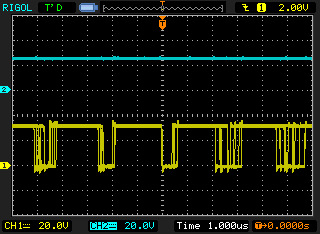
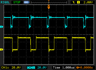
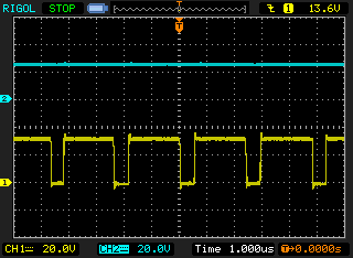
I am using a LM5177DCPR in a Buck-Boost application. I am seeing strange bi-modal behavior which I cannot explain.
I have two questions:
1. What is causing this bi-modal draw of excess current.
2. Should the IC be getting this hot?

The output voltage is set to 24V.
This is how I can recreate the anomally:
1. At start up, the converter is running off 31V input with no load; it is drawing 80mA. (top of chip temp = 57C)
2. I switch the input voltage to 28V and increase the load to 100mA for 5 minutes. (top of chip temp = 74C)
3. I switch the input voltage back to 31V. The input current goes up when I would expect it to go down.
4. I remove the load and the input current is 200mA. It does not return to the lower current draw in step 1. (top of chip temp = 82C)
5. If I quckly restart the system the higher current draw remains.
6. If I power down long enough for it to cool off, the no load current draw goes back down to 80mA.

4135.Power.pdf

  • Hi Paul,

    Thanks for using E2E. Response will be delay due to public holiday, please expect feedback on Friday. Thanks. 

  • Hi Paul,

    thank you for using the E2E forum

    The schematic shows the load should be a Motor. Are you using a Motor for this tests or another load.

    Can you provide some scope plots of the different conditions listed above ; showing below signals with ~5 switching cycles and ~ 5 ms time/div

    - VIN 

    - VOUT

    - SS

    - COMP

    Best regards,

     Stefan

  • I am sorry,  I can no longer reproduce the effect.  The unit now always powers up in the higher current state.  


    [FYI, The temperature does not seem to be a relevant variable - using cold spray did not seem to have any effect. ]
    [I am using a lab programmable electronic load, but that is not relevant because.my question is about operation at no load.]

  • I was finally able to reliably reproduce the two power conditions.  These are the captured waveforms for the hi power mode and the low power mode.

    .Captured Waveforms.pdf

    Background:

    My  LM5177 converter is fed from another DCDC converter through a hi-side switch.
    I was able to reliably create the high power draw by replacing the hi-side switch chip with a 1 ohm resistor.  
    With the 1 ohm resistor the converter always starts up and stays in the high power mode.  In the normal circuit it may start up in either mode and it may spontaneously switch into the high power mode.  However I have never seen it switch from high power to low power mode.

    Note that I tried putting a large (2200uF) electrolytic cap on the input of the  LM5177; but it did not prevent it from starting in the high power mode. 

  • More information:
    I changed the Slow-start capacitor to 0.1uF.  This caused the converter to again start up in the low power mode even with the 1 ohm series resistor on the input.
    However, when I applied a 200mA load the converter flipped into the higher power mode and stayed there. 

    My question is:
    Is this because it reduced the peak start up current?  or does adding capacitance to the ATRK pin improve overall stability? Both?

  • Hi Paul,

    the device will enter PSM mode on a 10% or 15% threshold. With the selected setting you did via CFG pin the threshold is set to 15% of the peak inductor current limit.

    Based on your schematic the peak inductor current limit is set to 50A  ( 50mV / 1mOhm).

    So if the sense resistor on CSA/CSB detect a peak current below 15A it will enter PSM mode. 

    If you are close to this limit in normal operation the SS (Softstart) can have an impact there. If softstart is slower the inrush current into the power stage is lower and then could be low enough to keep the device in PSM mode.

    Also with the 1Ohm resistor in the input you add some voltage drop which forces the power stage to a higher inductor current (due to lower input voltage).
    Assuming the input voltage before the 1Ohm resistor stays constant.

    Note: this is not a fixed value and some hysteresis is build in to not continuously jump in and out.

    Best regards,

     Stefan 

  • I don't think the  PSM mode is enabled.  The MODE pin is under processor control and is set high (3.3V) during operation of the converter.  I think that this should put the converter is "Forced PWM Mode" at all times?

    In any case, if PSM were enabled, should the converter ever exit PSM mode with NO LOAD?
    And once it enters the higher power mode - it never drops back to the low power mode.

    Is there something in my waveforms that suggests this is happening?

    Is there a minimum load when in "Forced PWM Mode"?  How is the output voltage maintained if the load current drops below the minimum? 

  • Hi Paul,

    sorry - was assuming that the device is set to PSM mode based on the pull down on the MODE pin in the schematic.

    Do you have the option to probe the inductor current and the signals on SW1 and SW2?

    Best regards,

     Stefan

  • I don't have a current probe; so I am not sure how to measure the inductor current.  But here are the switching nodes for the low power and the high power modes.  Trace 1 = SW1, Trace 2 = SW2
    Note: Both modes are with no load.

    Low Power Mode

    Low Power Mode

    High Power Mode

  • Hi Paul, 

    can you set the trigger edge to the falling edge for the low power plot.

    As you can already see from the plots, the device in one condition is in Buck mode and in the other in BuckBoost.

    Thanks,

    Stefan

  • It is set to the falling edge of trace 1 (SW1).  Do you want me to set it to the falling edge of Trace 2 (SW2)? 

    I do see that the trigger level is poor.  I will recapture with a better trigger level.

  • Why would it go into buck-boost mode?  The input is 30V and the output is 24V.  And why would it stay in that mode?

  • Hi Paul,

    the transition voltage can be up to 34 V for your configuration

    Transition Vin
    Buck -> BuBo 27.094135
    BuBo -> Buck 34.6176803
    Boost -> BuBo 21.2592135
    BuBo -> Boost 16.6388965

    Best regards,

     Stefan

  • So this is expected behavior?

    You say, "for your configuration". Is there something I can change to control this behavior?
    This mode change doubles the no load power consumption.

    I will test using the Power save mode; I was leaning away from it because my application has large sudden changes in load current.  I was not able to obtain any quantitative data about the difference between PSM and Forced PWM.

  • Hi Paul,

    the only parameter you can influence here is the switching frequency.

    Best regards,

     Stefan