This thread has been locked.

If you have a related question, please click the "Ask a related question" button in the top right corner. The newly created question will be automatically linked to this question.

LM61495: Inductor Selection

Part Number: LM61495

Tool/software:

Hi,

I am currently in the process of designing a buck converter using LM61495 to step down my 8s Li-ion pack voltage from 29.6V to 5.3V. The rated current is around 2A and the peak current is about 7A. I will assume a 10A of max current so we have some safety margin. 

Then, I put my requirements into the TI Power Designer to get some initial ideas and I was recommended the following topology where a 560nH output inductor was used:

I then double-checked the datasheet of LM61495 and encountered equations 5 and 6 which are both used to determine the required output inductance.


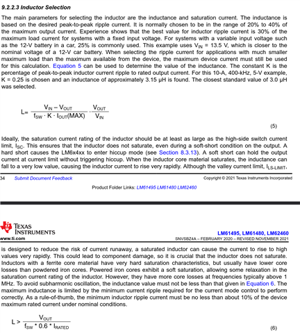
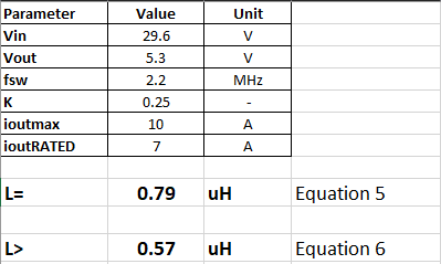
Assuming Fsw = 2.21MHz, K = 0.3 and Imax = 10A, we get L ~= 660nH using Equation 5. If we use  K =0.25, then it becomes 790nH.

However, my typical current draw is about 2A which means I would need a inductance of 2uH based on eqn 6. Given there is a such large discrepancy, which equation should i use to find my required output inductance?

Thank you so much in advance!

  • Hi Robin,

    The inductor is selected based on the max rated current of your design. In your case that will be 10A (or 7A). 

    You can also refer to this e2e post: https://e2e.ti.com/support/power-management-group/power-management/f/power-management-forum/1320123/lm61495-inductor-value-selection

    Furthermore, designing with LM61495-Q1 for a max current of 10A at 2.2MHz may lead to thermal limitations. Please look at the junction temperature rise in WEBENCH to get an understanding (alternatively - input the max ambient temperature of your design requirements and check the device performance). 

    You can also use the Design Calculator for this device (https://www.ti.com/tool/download/SNVR498).

    Thanks,

    Best Regards,

    Taru

  • Hi Taru,

    Thank you for your reply and suggestion!

    I am well aware that I need to pick an inductor based the max rated current of my circuit but I also need to know what inductance I need for my circuit. Eqns 5 and 6 are giving me conflicting results. The post you referenced mentioned that, "Usually for current mode control devices, subharmonic oscillation happens when steady state operation duty cycle is above 50%." Does that mean I can ignore eqn 6 and only use eqn 5 to determine my required inductance since my application will be stepping down from 24V~34V to 5V, which will have a duty cycle less than 50%?

    I have also checked Power Designer simulation results and there will be a 75C IC temp raise when running at 10A, which leaves me a lot of margin before thermal shutdown kicks in. Plus, I will only be running at 7A max for a few seconds. Do you think that will cause any problem?

    Thank you so much in advance!

    Best,

    Robin

  • Hi Robin,

    I am well aware that I need to pick an inductor based the max rated current of my circuit but I also need to know what inductance I need for my circuit. Eqns 5 and 6 are giving me conflicting results. The post you referenced mentioned that, "Usually for current mode control devices, subharmonic oscillation happens when steady state operation duty cycle is above 50%." Does that mean I can ignore eqn 6 and only use eqn 5 to determine my required inductance since my application will be stepping down from 24V~34V to 5V, which will have a duty cycle less than 50%?

    Yes. 

    For your use case - 


    As mentioned earlier, please use the design calculator - it shall make things simpler for you. 

    I have also checked Power Designer simulation results and there will be a 75C IC temp raise when running at 10A, which leaves me a lot of margin before thermal shutdown kicks in. Plus, I will only be running at 7A max for a few seconds. Do you think that will cause any problem?

    This is completely dependent on your use case.

    A 75 degC rise in temperature leaves you with a max ambient temperature of 75 degC (Max Junction Temperature - Temperature Rise in the IC; 150degC - 75 degC). If this works for your application - you can definitely go ahead. Your board thermals will also play a large part in it. From the perspective of the device - as long as you do not exceed the max junction temperature - you should be okay!

    Thanks,

    Best Regards,

    Taru