Tool/software:
In the datasheet of TL431, the schematic diagram of the reference comparator circuit is as follows.
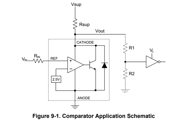
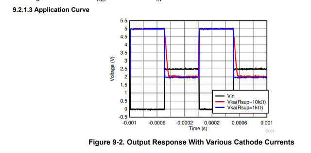
In the following comparison of the response time and the change in cathode current in the corresponding circuit diagram, it can be seen that the output of the cathode is 2V, and the input of the comparator is 2.5V. However, in the previous circuit schematic diagram, it can be seen that the cathode is connected to the power supply rail of the TL431 operational amplifier. Therefore, the power supply of the TL431 is 2V, but the input is 2.5V at this time. May I ask, shouldn't the input voltage of the operational amplifier exceed the power supply rail? Why can the TL431 be used in this way? Please ask TI to answer this question. Thank you! In addition, are there any other limitations for the application of the TL431 comparator besides what is stated in the data sheet?