This thread has been locked.

If you have a related question, please click the "Ask a related question" button in the top right corner. The newly created question will be automatically linked to this question.

TPS65219: TPS6521901 has no output and needs help to review the schematic diagram

Part Number: TPS65219

Tool/software:

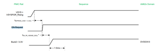
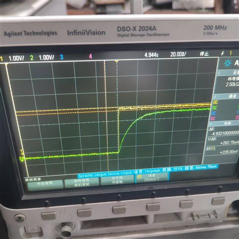
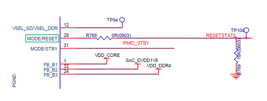
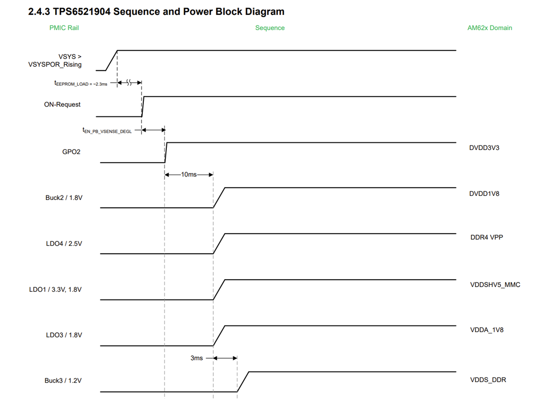
In the AM6254 core board reference. After the TPS6521901 is powered on, there is no voltage output. I need to help review the schematic diagram. Even when the TPS6521901 is changed to TPS6521904, there is still no output. thank you65219_ PAGE2(3).pdf

  • Hello,

    Thank you for using E2E! After reviewing the attached schematic, could you please clarify which Bucks or LDOs on the TPS6521901 are providing no voltage output?

    One small note is that the PVIN_B1_1 and PVIN_B1_2 pins share a single 4.7 uF capacitor. Could you clarify how these capacitors are distributed for the Buck inputs?

    Thanks,

    Matt

  • None of the BUCK and LDO outputs! The capacitors are all configured with 4.7UF and are shared.

  • Hello,

    Thank you for the clarification! As a follow-up, what is the configuration for the MODE/STBY pin? If the pin is configured in STBY, the output rails could be disabled for the TPS6521901.

    Also, are you using any I2C programming for the TPS6521901 PMIC?

    Best,

    Matt

  • MODE/STBY remains at a low level. Since the SOC has not been powered on yet, I2C is not operating.

  • Hello, 

    Are you able to provide more information on how this "PMIC_PBn" is sourced, and its status (HIGH/LOW) ?
    By default, EN/PB/VSENSE for the TPS6521901 is configured as EN, not PB. 

    Are you able to capture the timing of VSYS and the EN/PB/VSENSE pins going high on an oscilloscope?

    EN needs to be high within 120 us of VSYS for a valid on-request to go through. 

    Best Regards, 
    Sarah

  • Are there any recommendations for the peripheral RC circuits of EN/PB/VSENSE? Does an effective ON-Request refer to a high level of EN/PB/VSENSE? Is there a minimum time requirement for VSYS to be powered on to the high level of EN? I see there is an EEPROM_LOAD process?

  • Hello,

    Thank you for your response. I have added responses to your questions below. Please let me know if you need additional information:

    You said: 

    Are there any recommendations for the peripheral RC circuits of EN/PB/VSENSE?

    Which configuration would you prefer to set the EN/PB/VSENSE pin to? To ensure the EN/PB/VSENSE pin is in the default enable mode (EN), you'll need to pull the pin high by implementing a pull-up resistor. 

    You said: 

    Does an effective ON-Request refer to a high level of EN/PB/VSENSE?

    An ON-Request may refer to multiple things depending on what the EN/PB/VSENSE pin is configured to. If the pin in configured as EN, then a high level refers to an ON-Request. 

    You said: 

     Is there a minimum time requirement for VSYS to be powered on to the high level of EN? I see there is an EEPROM_LOAD process?

    In the power-up sequencing diagram attached, the tEEPROM_LOAD indicates the amount of time required for the PMIC to read its memory and load the EEPROM registers upon initializing. The remainder of the power-up sequence can only be executed after the EEPROM is loaded.

    As a follow-up to the failed rail output voltages, could you please provide oscilloscope readings of the VSYS and EN/PB/VSENSE going high? Also, I would like to analyze how the TPS65219 is powering up. If the power-up sequence is interrupted, the TPS65219 will attempt to power up two more times before remaining in the initialize state. Could you also provide scope readings of the output rails during the power-up sequence? 

    Best,

    Matt

  • Yellow is VSYS and green is EN.

    Pulling up EN is 100K.

    The VDD1P8 has an output of 1.8V, while the rest of the LDO and BUCK have no output.

  • Hello,

    Thank you for providing an oscilloscope shot! Yes, it appears the EN/PB/VSENSE pin is in the enable mode and is powering up normally.

    Upon closer review of the schematic, is there any reason why RESETSTATz is pulled to GND at TP122? I would recommend pulling this high and checking if the rails provide any output.

    Best,

    Matt

  • Hello,
    My problem has not been resolved yet. We have re-welded the small board (only the electrical and soft parts). The schematic diagram is as follows. It still doesn't work. I hope you can point out the problems in the schematic diagram.4251.PAGE2.pdf

  • Hello,

    I'm sorry to hear your issues is not yet resolved. Thank you for providing an updated schematic!

    For the MODE/RESET Pin (28), please try pulling this pin high and verify if the rails provide any voltage output.

    Best,

    Matt

  • It has been tested, but there is still no output

  • Hello,

    Thank you for testing my suggestion. 

    In the second schematic diagram provided, is the TPS65219 PMIC still attached to the AM6254 Processor? If not, can you validate that the PMIC provides voltage output with the output pins disconnected from the AM6254?

    Best,

    Matt

  • The PMIC is not connected to any load, and all pins have no voltage output, except for VDD1P8 which has a 1.8V output

  • Hello,

    Thank you for the clarification. I would recommend performing the following to diagnose the issue:

    • Keep the MODE/RESET pulled high.
    • For the TPS6521904, the EN/PB/VSENSE pin should be enabled as PB. If you have a push button attached to the PMIC_PBn netlist, can you try pulling this pin to GND for a minimum of 600ms by enabling the push button? 
    • To better understand the power-up sequence, can you please provide scope shots of VSYS, GPO2, Buck2, etc., upon the TPS6521904 powering on?

    Best,

    Matt