Other Parts Discussed in Thread: TPS25751, USB-PD-CHG-EVM-01, TPS25750
Tool/software:
Hello Team,
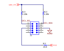
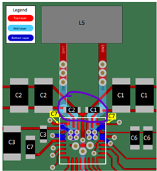
I am working with the TPS25751D PD controller along with the BQ25798 battery charger on a custom board based on the i.MX8ULP EVK.
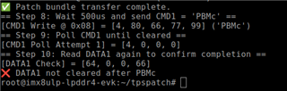
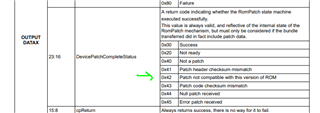
I have used the USBCPD Application Customization Tool to generate a patch binary and followed Figure 5-1 of the TPS25751 Technical Reference Manual (TRM) for pushing the patch bundle over I2Ct. The patch download process completes successfully (checked using CMD1 and DATA1 validation).
However, when I provide voltage through the USB port, battery charging does not start, and the STAT pin continues to blink at 1 Hz, indicating a fault or an abnormal condition.
Could you kindly suggest:
-
Any recommended register reads (e.g., CHRG_STAT, TS_STAT, INT_FLAG, etc.) to diagnose the cause of this behavior?
-
Are there any initialization steps required after patch download before the charger becomes fully functional?
-
Any possible configuration issues in the generated patch (e.g., IINDPM, VINDPM, charge current/voltage)?
-
Could incorrect TS pin voltage or NTC configuration prevent charging?
Any recommended checklist or diagnostics procedure would be greatly appreciated to help debug this issue.
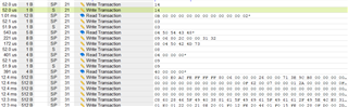
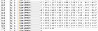
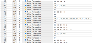
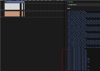
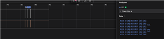
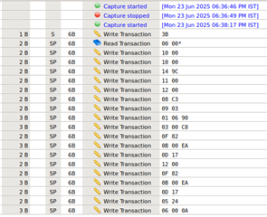
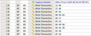
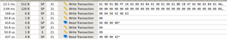
I am also attaching the I2C packet capture from the logic analyzer taken after the patch download was completed.
Thank you for your support.
Regards,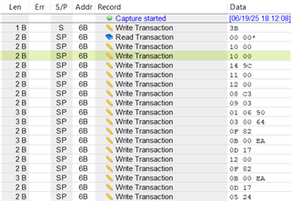
Aditya Patil