This thread has been locked.

If you have a related question, please click the "Ask a related question" button in the top right corner. The newly created question will be automatically linked to this question.

TPS6594-Q1: TPS6594 - nRSTOUT question

Part Number: TPS6594-Q1
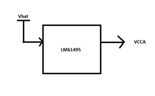
Other Parts Discussed in Thread: LM61495

Tool/software:

Hi, TI team:

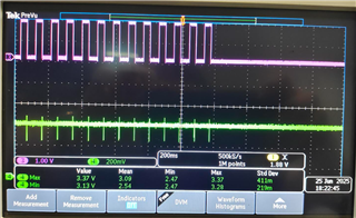
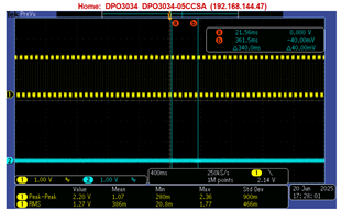
When I tested TPS6594-PMIC chip, and we found when Vbat in the 3.97V, PMIC-25 Pin( nRSTOUT ) will change 0--1.8V, but never change to 0V, please find this picture.

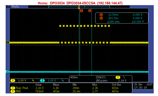
when Vbat in the 4.05V, PMIC-25 Pin( nRSTOUT ) will change 0<-->1.8V period, then will change to 0V, please find this picture.

Could you tell what will cause PMIC nRSTOUT pin still change, never to be 0V,  and what will cause PMIC nRSTOUT pin changes sometimes, then will be 0V later? it depends PMIC output current? 

because the Vbat 3.97V, current still change 0.2<-->0.4A,

when the Vbat is 4.05V, the current change 0.2<-->1.5A, then PMIC reset, current is 0.012A

  • Hi Rocky,

    To start with, can you please let us know which TPS6594-Q1 OPN or long part number you are using? This will help us know what configuration is already set in the device NVM so we can answer better. 

    Regards,

    Katie

  • Hi, Katie:

    this is MPN: TPS659414CFRWERQ1

    as I remember, if I change this register value = 0, and PMIC will still infinite recovery attempts until the error is removed?

  • Hi, Katie:

    Could you tell me my RECOV_CNT_THR = 0xf, why it happened PMIC will still infinite recovery attempts? please see my first question.

  • Hi Rocky,

    Two questions:

    1. Do you have a safety FET in your system?
    2. Additionally, can you show us VCCA during the sequence of events for the infinite case and the 15x count case from your original post?

    It would help us to check the sequence of events. The theory relates to the fact that this OPN supports both 5V and 3.3V and checks this as part of the wait4enable section of the PFSM.

    • In the NVM, VCCA_PG_SET starts at 0x1 or 5V at startup. 
    • When voltage is first applied to VCCA that is greater than UVLO, the PMIC sets VCCA_VMON_EN high, turning on monitoring.
    • It then checks the INT_VMON register to check current VCCA level - if VCCA indicates undervoltage, then the device will switch VCCA_PG_SET to 3.3V. 
    • For 3.3V, the OVP rising threshold is 3.9V to 4.1V which resembles the range we are indicating, so OVP mechanism is going to kick in. 
      • If you have safety FET and it closes and VCCA drops past UVLO, then this will reset the recovery count which is why you never hit threshold

    So the thought would be if your voltage at startup is not high enough fast enough, the PFSM assumes 3.3V operation. But your voltage could still be high enough that it triggers OVP for 3.3V, and with safety FET if you then drop past UVLO you will have cleared the recovery count. The solution would be to make sure that VCCA ramps faster so that it is above UV level for 5V when the check occurs so that PFSM doesn't choose wrong VCCA_PG_SET. 

    Can you help show us your VCCA in the two cases and comment about safety FET so that we can confirm the theory and then start working with you on solutions? 

    Regards,

    Katie

  • Hi, Katie:

    1: I don't know we have or not safety FET, but you can check our SCH.

    2: I tested VCCA in the two conditions, pink color is reset, green color is VCCA

    this is PMIC recover 15 times. you can see the VCCA dropped to 3.13V when PMIC restart, and when PMIC reset to 0, VCCA will become to 3.3V.

    this is VCCA when PMIC still restart, never become to 0. Could you tell me why it happened this?

  • Can you also give a zoom of just one of the cycles for each case so I can see more detailed the VCCA behavior? Are you seeing both cases VCCA is at 3.37V - I thought in your issue description you mention 3.9 and 4.05? What is your target voltage for VCCA? 

  • Hi, Katie:

    My VCCA voltage is 3.3V,  and 3.9V / 4.05 is Vbat, Vbat will though DCDC to VCCA.

    LM61495 is 12V to 3.3V, and we will raise Vbat from 0V to 12V, but when the Vbat = 3.9V, the PMIC will still restart, then Vbat = 4.05V, the PMIC will restart 15 times, and reset.

    the test requirement can not allow us to set the Vbat slew up rate fast. 

    1: Why is the RECOV_CNT_THR = 0xf, but PMIC still restart, never become to 0?

    2: I want to let PMIC still restart, never become to 0,  how many methods can we do it? I only know change RECOV_CNT_THR = 0x00;

        Do we have other methods? such as changing other register value to achieve it?

  • Can you zoom in on VCCA and nRSTOUT to show a single or at most 2 cycles?

    It looks like nRSTOUT is high for about 40ms every time. Can you confirm?

    If you look at the power rails of the PMIC, do they all shut down at same time as nRSTOUT? Or does it execute an orderly shutdown sequence?

  • yes, the nRSTOUT time is 40ms, could you tell me how to change this time? if we rise this time from 40 to 100ms or bigger, we can solve this problem.

  • Hi, Michael:

    do you have any feedback?