This thread has been locked.

If you have a related question, please click the "Ask a related question" button in the top right corner. The newly created question will be automatically linked to this question.

BQ34Z100-G1: RemCap Adjustment in Relax Despite no QMax Update

Part Number: BQ34Z100-G1

Tool/software:

three Tierra Rejada cycles 1 hour rest June 19 2025.logGotion Relaxation Log Post VCal.log

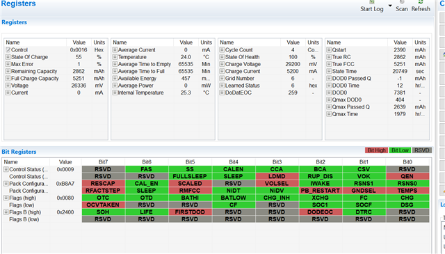
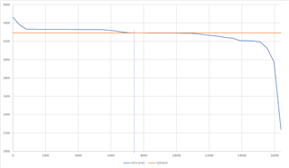
I am trying to understand why the gauge would make a remaining capacity adjustment while in the flat region and relaxed. I am working with chemID x4201, a 104AH LiFePO4 cell, and a golden image I had successfully acquired using said chem ID. My pack configuration is 16 series 1 parallel, and the shunt size is 50 micro-ohms with a design energy scale of 20. I began with my battery nearly fully charged at 99% SOC and ran three successive dynamic discharge cycles (each cycle is a net ~21 AH discharge, although each cycle contains some short regenerative charge currents). I only allowed on hour between each cycle and therefore never allowed the battery to relax. After 3 the third cycle and before relaxation, the gauge registered 41% SOC, which was satisfactorily accurate within 3% points of expected SOC. After a relaxation period, the gauge increased the SOC by 1% to 42%. I would like to understand why this adjustment is made. The battery is still in the flat region and no QMax update has been made since the start of the three discharge cycles. The VOK bit remains set, the OCVTAKEN bit remains clear, and the FIRSTDOD bit are set, which indicate to me the battery has entered relax mode but no qualified open circuit voltage for a QMax update has occurred. If no QMax update occurs, how can the remaining capacity be adjusted upwards slightly which triggers a 1% increase in SOC? Attached is the log file of each of the three successive dynamic discharge cycles and then a subsequent relaxation log which captures the 41 to 42% SOC adjustment

Please note as well that in between the three discharge cycles and relaxation log, and the relaxation only log, I noticed the gauge voltage reading was slightly off by 80ish millivolts and I re-calibrated it. This is why the voltage suddenly seems to increase

  • The gauge will re-adjust RM if it takes an OCV measurement (which is after a significant timeout for LFP cells esp. if charging stopped in the flat OCV zone) but also if temperature changes by more than 5 deg.C.

  • I thought RM was not adjusted in the flat region of the SOC to OCV curve for the chem ID? Being as this is a LiFeP04 cell, and each cell voltage was above 3V (around 3.25V), wouldn't RM adjustments due to OCV be disabled? Also, the max temperature delta reached during discharge vs. relax never exceedd 3 degrees C and I do not see the "Remaining Capacity Adjusted Due to Temperature" Bit Being set.

  • Hey Dominik,

    It has now been 5 days since the discharge cycling has ended, and the SOC has increased all the way to 55%. This is despite the QMax time indicating no QMax update has occurred in 5 days, which is when cycling ended. During these 5 days it seems that an OCV was taken in relaxation as the OCVTAKEN bit became asserted and the VOK bit cleared. The DOD0 value now has jumped greatly since the DOD0 value prior to this OCV reading was last taken near 100% SOC. Although we are using a TI characterized chem ID our SOC has now jumped to 55% when it is expected to be 41%. Can you point me to any reason this huge correction would have been made in relaxation based on OCV? We are using chem ID 0x4201 which was provided to us but it has generated a massive error. I have attached a csv of the data flash as wellgotion_104AH_data_flash.gg.csvGauge Registers after 5 Days of Relaxation

  • The gauge will force an OCV measurement after 172800 seconds in relax (=48 hours). Note that this will not necessarily qualify for a Qmax update but it will update DOD0 and as a result it will update SOC.

    >The DOD0 value now has jumped greatly since the DOD0 value prior to this OCV reading was last taken near 100% SOC. 

    How much did DOD0 change? What is DODatEOC?

  • Thanks for the fast reply Dominik. DOD0 5 days ago after the three discharges was 404, the DOD0 value now is 7381. The 404 for DOD0 was constant both before and after the three discharge cycles, which makes sense to me as we only allowed the battery to relax for an hour before beginning the subsequent discharge cycle and after the charge to full (no relax = no DOD0 OCV measurement taken, no QMax update etc). DoDAtEOC is now 259, and 5 days ago after the three discharge cycles it was 244. Before the three discharges (it was @99% before the 3 discharges) the DoDAtEOC was 208.

  • The problem with this is that the cell's relaxed voltage falls into a voltage zone where the ChemID can't resolve DOD accurately.

    Here is the OCV for ChemID 4201 for a single cell together with the single cell voltage from our screenshot:

    That's why the gauge adjusts this to DOD0 = 7381.

    "now jumped to 55% when it is expected to be 41%."

    Why was it expected to be 41%? Did you discharge to 41% or charge to 41% and then let it relax?

  • I was under the impression from reading the Impedance Track notes that OCV measurements in the flat region don't modify Remaining Capacity? I guess that's incorrect.

    "Why was it expected to be 41%? Did you discharge to 41%"

    We are using this chip for an application that involves dynamic loads, I.E. regen charging and quickly changing discharges. Our test equipment allows us to run sequences which are identical to a real-life dynamic load involving some regen charges and discharges. This particular sequence lasts about 50 minutes and generates a net loss of about 21AmpHours. Three of these sequences were run. Being as this is a 104AH cell, running three sequences which each are equivalent to a net discharge of 21AH should end up leaving the battery at about 40% since each sequence decreases the SOC about 20%. After each dynamic load sequence, the SOC dropped 20% from the starting point, so the gauge was able to integrate charge and discharge correctly. We did not let the battery relax in between each 50 minute net discharge sequence. 

  • Is there no way to prevent DOD corrections causing large SOC changes in relaxation? It seems there must be, else anytime you have the battery relaxed in a flat region of the OCV curve the SOC may drastically change

  • The gauge will not use OCV in the flat region for a long time. For example, if you charge into the flat zone, it will wait for at least 48 hours before it adjusts DOD0. It definitely will update RM and RSOC. It will not allow Qmax updates in the flat zone (that is probably where the misunderstanding comes from).

  • The gauge will try to minimize DOD errors in flat zones. But this must be enabled. Please make sure that Pack Configuration B, Bit 1 (DoDWT) is set to 1.

  • We do have bit 1 in Pack Cfg B asserted, you can see that in the data flash .csv attached…are there any other config bits I can set to prevent long rest periods leading to OCV DOD adjustments? Our product will be loaded and then sit idle for a few days, since it’s a motive battery so this is a bit of an unavoidable phenomenon 

  • Hey Dominik, also we do have RELAX_JUMP_OK set to zero, so how is a jump like this even possible? 

  • If you have smoothing enabled and you do not reset the gauge or the algorithm then SOC will not jump in relax if RELAX_JUMP_OK is 0. Please make sure that the gauge is indeed in relax state (check Dsg Current and Quit Curent Thresholds). Note that a short change in state will cause SOC to adjust.

  • 1.The register states after the jump to 55% don’t indicate any reset. My QMaxTime for example kept incrementing forwards in time relative to the last QMax update nearly a week before. Unless I am mistaken wouldn’t that be a register that would reset have reset to zero since no QMax update would have occurred after reset without a substantial charge or discharge?

    2. I have zero’d this gauge and the deadband is high enough (400mA) that I have never seen any noise that causes the gauge to read a non-zero current measurement in idle. I have zero’d this gauge. But, I am confused a bit. I see in the log in when the first correction occurs which moves the SOC from 41 to 42% the QMaxPassedQ continuously decreases although the current is zero; it seems this decrease continues, beginning from 3055 at the end of discharge to 2639 by the time the jump to 55% occurs. Again, this seems decoupled from any non-zero current measurement: How could this be? I was under the impression any current below the deadband wouldn’t be integrated

  • #1: Please make sure that the gauge was in the correct state (relax) all the time. The Quit Current Threshold should be set to C/25 and the Dsg and Chg Current Thresholds should be set to C/15.

    #2: If QmaxPassedQ changes then the gauge at least "measured" an error (non-existing current). The current deadband doesn't mean that the gauge rejects any current below this number. All it does is report 0mA for a current that is below this setting. If you set this to 400mA then the gauge will still accumulate passed charge if it measures <400mA (e.g. if it measures 399mA then it will accumulate 399mAh in one hour) while reporting a zero current.

  • Thanks Dominik, point 2 is a good one. Any chance you would know how what the maximum CC_Offset value obtainable is when using a 50 micro-ohm shunt in terms of mA of current? I just am interested in knowing how much noise can be suppressed when zero’ing the gauge based on the width of the CC_Offset register and that shunt size. There was no load attached at all to the battery while it was sitting and there have been issues with this very small shunt being sensitive to Noise in the past 

  • The maximum CC Offset value correlates with the maximum offset error for this gauge. TI doesn't specify the maximum. The typical is 10uV so you'd have to calculate what this means in units of mA for your sense resistor.

    The gauge will auto-calibrate CC Offset so this value will change over time. It does this before entering sleep mode (if the current is below the sleep mode current threshold and sleep mode is enabled).

    The gauge will auto-adjust cell state (depth of discharge) when the battery isn't being discharged with a significant current. So any noise should not matter - the gauge will re-set coulomb count automatically when it takes an OCV measurement.

  • >The typical is 10uV so you'd have to calculate what this means in units of mA for your sense resistor.

    Our shunt is only 50 microOhms, so this would already be 200mA. The current quit current threshold configured is 500mA, and the charge/dsg thresholds are only 600mA. For what it is worth, we have another application that uses a 100 micro ohm shunt and a 3.74x amplifier; With this larger shunt and amplifier, we don’t see these fluctuations in SOC at relaxation and all of the gauge configurations are the same

    The recommended C/x rates you have mentioned for quit and charge/dsg current thresholds. May I ask where those recommended values come from? I’ve not seen those in the TRM. What are the ramifications of having too low of a charge/discharge quit threshold for gauging during relax relative to battery capacity (the battery in question for these logs is 104AH)? 

    >The gauge will auto-adjust cell state (depth of discharge) when the battery isn't being discharged with a significant current. So any noise should not matter - the gauge will re-set coulomb count automatically when it takes an OCV measurement.

    But if RELAX_JUMP_OK is set to zero, and we are in the flat region, this would not occur, correct? Considering the shunt size in this application is very small (50 micro-ohms), would it be a reasonable conclusion to make that based on the changing QMaxPassedQ value *increasing* while the battery is idle, there is a noise current larger than the maximum CC_Offset value for the gauge being integrated by the shunt in the charge direction? The difference in QMaxPassedQ at 55% after 5 days of rest and right after the end of discharge at 41% is about 9 AmpHours based on the logs. This doesn’t account for the entirely of the 13% jump, but I assume it plays a large role…The only piece of the puzzle that still doesn’t make sense to me is when and why the Remaining Capacity gets adjusted; Is it that the gauge has to exit relax mode for all the false charge integrated as reflected in QMaxPassedQ to update the Remaining Capacity? 


  • As a rule of thump, Quit current should be set to C/25. Dsg and Chg current thresholds should be set to C/16.

    This will prevent the algorithm from running code that isn't applicable for the cell state. So a 104AH cell should have a Quit Current of 4160mA and a Dsg and Chg current threshold of 6500mA.

    What this means is that a current of less than 4.16A will not cause a material voltage drop over the internal cell resistance, hence the voltage is equal to an open circuit voltage and the gauge should use OCV measurements to determine cell state.

  • Thanks Dominik for the Quit Current / Chg / Dsg Threshold Info

    "What this means is that a current of less than 4.16A will not cause a material voltage drop over the internal cell resistance, hence the voltage is equal to an open circuit voltage and the gauge should use OCV measurements to determine cell state."

    Okay, please correct me if my understanding is accurate now; Based off of this information, the fuel gauge will not make OCV adjustments in the flat region so long as the measured current is below the Quit Current threshold. If the current magnitude is less than Quit Current, only uncorrected OCV measurements are taken which effect the DOD0 value. As we have RELAX_JUMP_OK set to zero, the OCV measurements will update DOD but will not update SOC(?). If the magnitude of the current rises into the band between Quit Current and Chg/Dsg Threshold, an IR correction is done where OCV is calculated as OCV`=OCV-I*R. Still, even in this band, will RELAX_JUMP_OK not prevent SOC adjustments? Finally, if the current exceeds the charge/discharge threshold, the Integrated Passed Charge is *not zero'd* and DOD = DOD0 + PassedCharge/Qmax. The gauge at this poin has exited Relax Mode so SOC is re-calculated. So, if I am not mistaken then the SOC adjustment would only occur once the charge/discharge threshold is surpassed?

  • The gauge will take OCV readings in the flat zone (various timeout rules apply - the main one is that it will wait for 48 hours (default setting) if charging terminated in the flat zone). However it will not qualify OCV in the flat zone for Qmax updates. It will still update DOD0 and true SOC (it will keep smoothed SOC constant, unless enabled with RELAX_JUMP_OK) even with OCV measurements in the flat zone.

    >Still, even in this band, will RELAX_JUMP_OK not prevent SOC adjustments

    If RELAX_JUMP_OK is 0 then an OCV measurement will not cause SOC to jump. However, SOC will still change slowly with accumulated current.

  • Okay, so all this then is likely caused by the fact the shunt is 50 micro-ohms and the offset error of this gauge is 10uV, which is already 200mA of "current" plus any additional noise that could be coupling to the shunt. You did say PassedCharge is zero'd at each DOD0 update in Relax: Why isn't this sufficient to prevent charge integration in REST mode? Is there anyway to:

    - Disable current integration if the current is below a certain point
    - Outright disable current integration entirely

    Or, would you simply recommend that a larger shunt is used, say in the 100-230microOhm range? Our application needs to support currents up to 525A, and the full scale shunt measurement range is +/-125mV, so the max that could be used is 238 microOhms @ 525A to not exceed 125mV.

  • It's not directly possible to prevent charge integration. The error is so small relative to the size of the battery that an OCV measurement will always cancel it out by resetting DOD0. So there is no need to compensate for an offset error from the coulomb counter. The accumulated passed erroneous charge will be zeroed out anyways with an OCV measurement.

  • >The error is so small relative to the size of the battery that an OCV measurement will always cancel it out by resetting DOD0. So there is no need to compensate for an offset error from the coulomb counter. The accumulated passed erroneous charge will be zeroed out anyways with an OCV measurement.

    but my QMaxPassedQ value has changed significantly since relaxation..When you say that DOD0 resets it, does the accumulated charge since last DOD0 value not get added to QMaxPassedQ before it’s zero’d? If the OCV doesn’t update Remaining Capacity and passed charge apparently has no effect in relaxation, how does the SOC possibly change via Remaining Capacity changing? Isn’t the issue still accumulating integrated current during relaxation due to noise/offset?

  • The gauge uses coulomb count and DOD0 to determine the absolute discharge level of the cell: DOD = DOD0 + passed charge / Qmax.

    There are two main reasons why the gauge tracks passed charge:

    1. To always know DOD.
    2. To update Qmax, if there's a jump in DOD when the gauge takes an OCV measurement to calculate a new DOD0.

    #2 will only happen, if conditions are right (outside flat zone, temperature etc.)

    By definition, passed charge must be reset to 0 when the gauge updates DOD0, otherwise the equation from my first line wouldn't be true.

    The gauge doesn't use passed charge directly to update RM. Instead it uses a discharge simulation with present conditions (temperature, load prediction changes based on Load Select setting and past measurements) starting at the new DOD0. So it doesn't matter, if passed charge is set to 0 at this point. What matters is DOD0. I think one of the misunderstandings is that DOD0 can update in the flat zone (while Qmax cannot). If you wait long enough (5 hours timout in regular relax, 48 hours timeout in relax after charge into the flat zone for LFP), the gauge will update DOD0, it will reset passed charge, it will run a discharge simulation, it will update Remaining Capacity (and SOC and FCC), it will keep filtered Remaining Capacity, filtered SOC and filtered FCC constant, if the discharge simulation is > 0mAh and Relax Jump Ok = false.

  • 1. Is DOD0 the first well-relaxed OCV reading which updated DOD, or is it the most recent DOD update that occurs every 100 seconds after the initial DOD update at entry of relaxation? I guess what I am asking here is if DOD0 is supposed to mean the first well-relaxed OCV reading or if it is the most recent OCV reading (I know DOD updates every 100 seconds after the first OCV reading in relaxation)

    I think I understand what you mean about zero'ing Passed Charge: DOD0 is updated every 100 seconds after the first well-relaxed condition < 4uV/Second change condition / 48-hr timeout event occurs, so each DOD0 = DOD0_Prev + (Passed_Charge_Since_Last_DOD_Update) / QMax since DOD0 is integrating passed charge since last update (correct me if I am wrong). The noise current, if it is around 200mA, could accumulate enough over the course of 5 days to effect DOD0, no? 

    When do the discharge simulations occur? I thought they only occurred during a few points during discharge. I did not know they occurred in relaxation. Is it every time DOD0 is updated? 

    >, it will update Remaining Capacity (and SOC and FCC), it will keep filtered Remaining Capacity, filtered SOC and filtered FCC constant, if the discharge simulation is > 0mAh and Relax Jump Ok = false.

    Intetestingly, our TrueFCC and TrueRC are equivalent to compensated RemCap and FCC, despite RELAX_JUMP_OK being set to 0 after the 5 days of relaxation when the SOC has drifted upwards to 55%. Our Load Mode is set to 1 *but our Load Select* is set to 1 as well, which based on the TRM states:

    Present average discharge power: This is the average discharge power from the beginning of this discharge cycle until present time

    If we are in a relaxed state, and we have some noise such that the gauge flickers between 0/+-200mA, and the gauge begins a constant-power discharge simulation in a state where the gauge current is 0A, will this cause the TrueFCC and TrueRC to become equivalent to the filtered RC / True RC thus negating RELAX_JUMP_OK = 0? Would it be more advantageous to configure the discharge simulation to use a constant C / 5 rate instead?

    I suppose then it is possible DOD0 is continuously adjusted upwards due to a noise current being measured. The SOC adjusts upwards when a discharge simulation is run at DOD update where the gauge correctly measures 0A. If this occurs, filtered RC / FCC will become equivalent to True RC / True FCC? As DOD0 would have been slowly increasing relative to when discharge ended, then the prior simulations that occurred when the gauge measured a non-zero noise current would have calculated a higher True RC due to the fact the DOD0 value was decreasing, as QMaxPassedQ was increasing which indicates the noise current was largely in the charge direction. 

  • DOD0 keeps getting updated in relax so if the cell sits idle for a very long time, DOD0 will continue to update as OCV drops.

    Discharge simulations happen for many triggers. It's time, temperature change and voltage stability in relax. They also happen during state changes (e.g. relax to charge).

    DOD0 can be affected by current. The main criteria in relax for a DOD0 update are stable OCV and time. However, the gauge also measures current and adjust DOD0 using a modified OCV = measured voltage + measured current * estimated cell resistance. So it's possible for current to affect DOD0.

  • Right, that all tracks - but DOD0 updates in the flat region when the battery's measured current is below the charge/discharge threshold don't modify SOC in and of itself because we have RELAX_JUMP_OK set to 0. So then is the only way for SOC to be updated in Relax if RELAX_JUMP_OK is set to zero, and the current is < DSG/CHG thresholds if a discharge simulation occurs in which the discharge simulation is run at 0mWH? Furthermore, is it possible for the simulation to be run at 0mWH if Load Mode = 1, and Load Select = 1, and the current to be at true zero? I saw you mentioned that so long as the mWH/mAH used for the discharge simulation is non-zero, only the TrueRC/TrueFCC are updated, but not filtered RC/FCC. I would assume the opposite condition is true: If RELAX_JUMP_OK = 0, but the discharge simulation is run at 0mWH, then the filtered RCC and FCC are unified with the TrueFCC and TrueRC. 

  • Note that the bit says "Jump". What still happens in relax, if you set this bit to zero is, that measured current (even in error, like a non-existing current but e.g. offset error that isn't auto-calibrated to exactly zero) will add up so eventually you will see SOC change (but not jump) if this RELAX_JUMP_OK bit is set. This is usually a very long time effect, as in relax for a week or longer.

  • 1. Got it..Is there any sleep setting the gauge enters, short of total power loss or held in reset, that will prevent it from integrating charge in relax?
    2. If the discharge threshold is increased to C/15, and we have a load that pulls current at a lower C rate than C/15 but above C/25: Will the gauge still integrate current and update SOC when that small load is the only load?
    3. Is a C/50 level acceptable for taper current setting?