This thread has been locked.

If you have a related question, please click the "Ask a related question" button in the top right corner. The newly created question will be automatically linked to this question.

LMG1020EVM-006: Testing SCW 1637-250R using TI LMG1020EVM

Part Number: LMG1020EVM-006
Other Parts Discussed in Thread: LMG1020

Tool/software:

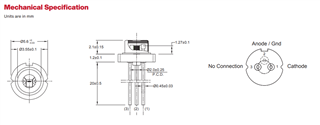
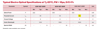
I am testing a pulsed laser diode (SCW 1637-250R) using TI LMG1020EVM driver board to generate short pulse width for laser diode.

I put this laser diode on LMG1020EVM board and applied Vbus from 1V and increased this voltage slowly up to 12V. But I don’t see any voltage changes at Cathode node of laser diode and also current changes (0A) from the DC power supply generator for Vbus voltage (The max current limit in power supply generator is set to 1A for Vbus voltage).

Since this laser diode operating 1625nm of wavelength, we used ThorLabs VIS/IR Detector card to see the laser light visually, but no light is shown in the Detector card.

The input signal to the gate of GaN FET (EPC2019) inside of LMG1020 chip has 5.5V, 20n sec of pulse width, 1u sec of repetition rate.

Can you know how I can make this SCW 1637-250R laser diode operate with TI LMG1020EVM board?

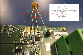
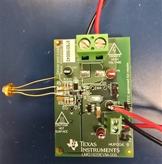
Here are some images from our test setup.

1. LMG1020 EVM board with SCW 1637-250R - Anode and Cathode are connected as LMG1020EVM manual suggested.

2. Yellow waveform: Input signal from arbitrary signal generator to LMG1020EVM board
Green waveform: IN+ voltage on LMG1020 (5.5V, 20n sec of pulse width, 1u sec of repetition rate)
Blue waveform: Vg on LMG1020EVM (gate voltage to GaN FET of LMG1020)
(please ignore the red waveform)

  • Hello,

    It is not entirely clear from the laser datasheet if the pinout is the bottom or top view. Have you tried switching pins 1 and 3 of the laser diode? Looking at other pinouts for similar parts, It looks like the connection might be incorrect.


    Thank you,

    Walter

  • Hello Walter,

    Please see the image below. I put node names of laser diode in the image for clear view. I am pretty sure the diode attached correctly.

    But I can try switching pin1 and pin3 if you are still not clear.


  • Hello,

    Have you tried switching the laser diode pins 1 and 3?

    Thanks,

    Walter

  • Hello Walter,

    Yes, I tried to switch the pin1 and pin3 of laser diode. (Please see the image below).

    Initially, there was no current (0A) measured at Vbus from supply voltage generator.

    After changing the pin connections (pin1 - pin3), I can see there is current flowing (49mA at 12V) at Vbus node.

    But still no light is detected using ThorLabs VIS/IR Detector card.

    Should I apply higher Vbus votlage? Any thoughts?

  • Hello,

    The typical threshold current for the laser diode is 45mA so there may be very little or no light emitted at 49mA.

    I would try increasing the current and set a current limit on the power supply below the max operating current.

    Thanks,

    Walter