This thread has been locked.

If you have a related question, please click the "Ask a related question" button in the top right corner. The newly created question will be automatically linked to this question.

TPS25763Q1EVM: Configuring PDO for USB Data Communication

Part Number: TPS25763Q1EVM

Tool/software:

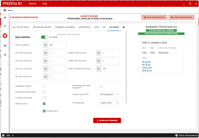
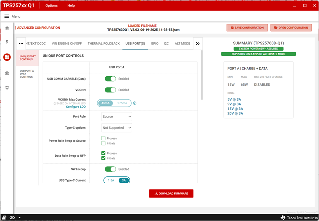
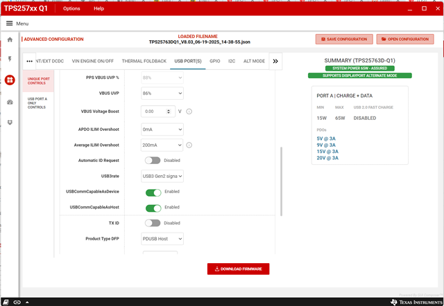
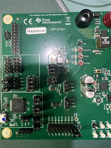
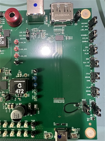
We have the TPS25763Q1EVM for evaluating the ability to charge a tablet while supporting data.  The tablet is plugged into J30 and charges properly.  We have a laptop plugged into J29 on the EVM.  We have tried a variety of USB Port/Alt Port configurations but the laptop will not enumerate the tablet through the EVM.  EVM jumpers are all set to the default positions and the R41 #OE jumper mod has been made.  Shown below are the latest EVM settings, which seem to make sense on the surface.  What is the proper configuration to support this charging + data scenario?

Thank you for your help.

Steve

  • Hello Steve,

    Thanks for your feedback, and here are a few comments:

    1. Based on your screen shot, the DP alt mode is not enabled, please confirm only data comm capability is needed.

    2. Currently the EVM only support USB 2.0. The system is designed to support USB3, but this is something we are also debugging on our end. We believe there is a trace length mismatch but have not been able to confirm the root cause. So first please change your config for a USB 2.0 data and use proper 2.0 cables for testing (USB 3.0 may has higher priority when it's supported on the laptop side). With a customized PCB design, the 763 will be able to support 3.0 USB data with proper DPDM trace design.

    Regards,
    Tianhao

  • Hi Tainhao,

    Our application is data comm with charging.

    I updated to "USB3 not supported" but still do not have communication between the tablet and laptop. Our test setup is straightforward:
    - connect laptop to tablet with USB type A to C cable and verify laptop enumerates tablet correctly.
    - connect USB C to C cable between EVM J30 and tablet and verify charging.
    - connect USB A to B cable between laptop and EVM J29.
    - expect tablet to be recognized by laptop but it is not.

    What is the proper configuration to support this charging + data scenario?

    Thank you for your help.
    Steve

  • Hi Steve,

    I'm also looking into this and plan to get back to you by Thursday. 

    The attached setting should be the proper one for charge+data, but can you please attach the .Json configuration file here for a double check?

    Which version of the base image are you using? Is it 04.01.0005? 

    Can you take a picture of the EVM so we can see the jumper locations?

    BR,

    Ke Wang

  • Hi Ke,

    The image is F411.04.01.0005.  Attached is the json file along with pictures of the jumpers which are still at their default condition when EVM was unpacked.

      TPS25763DQ1_V8.03_06-24-2025_12-26-11.zip

    Thank you for your quick response.

    Steve

  • There is no traffic on D+/D- when J29 is plugged into the upstream laptop.  It is not clear to me what the mechanism is to initiate data transfer as J29 VBUS only appears to go to the LED and D+/D- are passthrough all the way to J30.

  • Hi Steve,

    Currently I don't think there's anything wrong with your firmware. We need to wait for another colleague coming back from his OoO next Monday for further check.

    Thanks for your patience.

    BR,

    Ke Wang

  • Hi Ke,

    It is related to the downstream device on J30.  If I plug in an external USB-C hard drive or mouse, they are supplied with 5V and enumerate on the laptop connected to J29.  If I plug an Android tablet or Thinkpad into J30, they charge but there is no data transfer initiated.

    Looking forward to Monday's response.  Have a good weekend.

    Steve

  • Hi Steve,

    I had a discussion with a more experienced team member and seems it's an integrity issue that may happen this with this Rev A EVM. As you already know this board doesn't support USB 3.0, and seems sometimes the USB 2.0 communication might also be impacted.

    One more thing you can try is remove R54 (0-Ohm to open circuit) to increase the signal buffering capability, but we are not 100% sure it can build a reliable comm capability between cellphone and laptop. I may suggest starting with flash drive for the initial emulation of data transferring capability for this board. A optimized EVM might be release in the future.

    BR,

    Ke Wang

  • Hi Ke,

    Thank you for the info.  We can enumerate and external hard drive so the basic data channel is OK.  If you are comfortable the TPS25763 firmware settings are correct and the TPS25763 can support laptop to laptop/phone connectivity, then we will move forward with our custom PCB.  The EVM issue is trace length mismatch only or are there other known issues?

    Thanks again for your help.

    Steve

  • Hi Steve,

    Thank you for your understanding and the EVM USB data comm issue should be mainly due to the differential pair of DP/DM is not optimized. 

    Here are a few comments of the trace design:

    "USB data lines, DP and DM must be differentially routed between the IC pins and USB connector. Impedance control is based on the PCB stack-up. 90 Ω differential is recommended. Route the DP and DM USB signals using a minimum of vias and corners which reduces signal reflections and impedance changes. When a via must be used, increase the clearance size around it to minimize its capacitance. Each via introduces discontinuities in the signal’s transmission line and increases the chance of picking up interference from the other layers of the board. Be careful when designing test points on twisted pair lines; through-hole pins are not recommended. When it becomes necessary to turn 90°, use two 45° turns or an arc instead of making a single 90° turn to reduce reflections on the signal traces by minimizing impedance discontinuities. Avoid stubs on the high-speed USB signals because they cause signal reflections. If a stub is unavoidable, keep the length to less than 200 mm. "

    BR,

    Ke Wang