Other Parts Discussed in Thread: TPS65987D, TPS6598X-CONFIG, , TPS25751, TPS65987, TPD4S311A, USB2ANY
Tool/software:
Dưới đây là bài miêu tả hệ thống mong muốn của bạn, viết bằng tiếng Anh trang trọng, rõ ràng và phù hợp để đăng lên diễn đàn kỹ thuật hoặc gửi trực tiếp đến TI Support:
Dear TI Support,
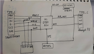
I am developing a USB Type-C dongle using the TPS65987D that needs to support the following functionality:
-
When a 5V power adapter is connected to the dongle:
-
The adapter powers the dongle.
-
The dongle charges the phone via USB-C at 5V, up to 2A.
-
At the same time, the phone must remain in USB Host (DFP) mode, and communicate with the dongle via USB 2.0 data lines (D+/D–).
-
-
When the adapter is not connected:
-
The dongle powers off completely (no data, no VBUS).
-
The phone must not power the dongle (to avoid draining its battery).
-
No communication should occur.
-
So, in short, the phone must always act as the USB Host (DFP), while also being a Sink (charging) when a 5V adapter is connected to the dongle. The dongle must never draw power from the phone.
We understand that this asymmetric configuration (DFP + Sink) is only achievable through USB Power Delivery (PD) and not through legacy CC pull-up/down.
Our intention is to:
-
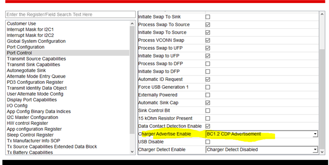
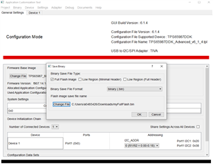
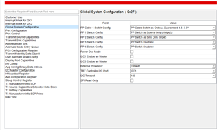
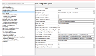
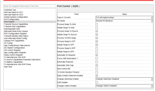
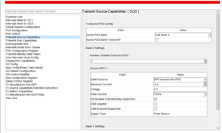
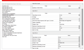
Use the TPS65987D in standalone mode with SPI flash (W25Q16JV) to store the PD configuration.
-
Generate a custom PD image using the TPS6598x-CONFIG tool, with:
-
DRP enabled, but default to UFP (Device) with Source role when adapter is present.
-
Advertise PDO: 5V @ 2A.
-
Force data-role = UFP (so that the phone remains DFP for OTG communication).
-
Disable VBUS sourcing unless adapter is present.
-
We will program the .bin configuration file into the SPI flash using an external MCU (STM32), then connect it to the TPS65987D via SPI.
Could you kindly confirm that this architecture is valid for the TPS65987D?
Also, if possible, please approve access to the TPS6598x-CONFIG Tool so we can proceed to generate the necessary firmware image.
Thank you very much for your support.
Sincerely,
[Mr.Hiếu]


 .
.