Other Parts Discussed in Thread: TPS562211,
Tool/software:
Hello:
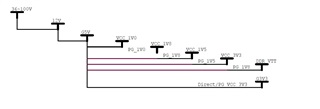
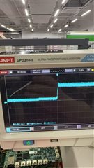
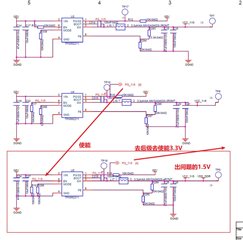
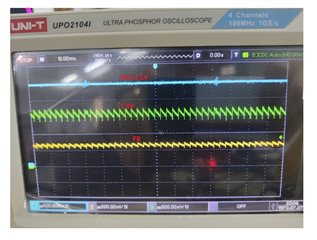
The customer originally used TPS562211 to convert 5V into various voltages (1.0V, 1.8V, 1.5V). Now the customer reported that after switching from TPS562211 to TPS562212, the ripple of 1.5V output was too large, mainly because the output ripple of the two pins VCC_1V5 and VDD_DDR was too large, causing the PG signal to become a square wave, which caused problems when enabling the subsequent 3.3 V circuit. After switching to TPS562212, the 1.0V and 1.8V circuits had no problems.
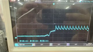
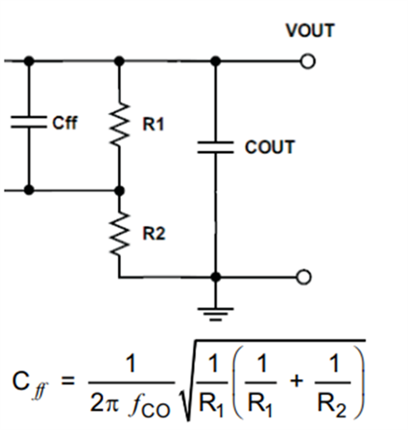
The customer suspected that the abnormal FB feedback bandwidth caused ripples in the startup phase. A 150uf capacitor was connected in parallel to the R289 resistor to increase the feedback bandwidth. After multiple tests, there was no problem for the time being.
The customer wanted to confirm whether there was a difference between the TPS562211 and TPS562212 in the application circuit. The only difference was in the Typical Application FB, 2211 is DNP, 2212 is 0 ohm R6, 10pf C7. The only difference was suspected to be related to the feedback bandwidth.
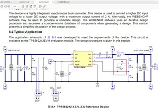
It is necessary to confirm the feedback bandwidth of TPS562212. What is the built-in feedback bandwidth, and what is the bandwidth range after adding 10pf.?Thanks!!!