


Tool/software:
Hello,
Is there a reference design where UCC27712 gate drivers are used to drive 100% duty cycle on both high and low side of transistors? I understand it needs a floating power supply to bias high side transistors' gate to source voltage but I wasn't sure how it's done exactly. Do I need to worry about low side transistor when driving it at 100% duty cycle as well? What happens if both are running at 100% duty cycle?
My application is brushed DC motor that is not based on PWM signals (instead static signals, either on or off sometime) and I am thinking of using 2 of these gate driver ICs + external transistors. Unfortunately, I am not able to use those great fully integrated ICs that TI supports in our application due to some restrictions.
*revised
I noticed another post about having this circuit (floating power supply). Is there anything that I need to be cautious when using below configuration? Any limitations? As mentioned above, I am using it as brushed DC motor driver where input is based on just discrete signals like either on for 10 seconds and off for 10 seconds. This will be done with combination of 2 of gate driver IC and 4 transistors. I wanted to confirm if there is anything that I need to be aware other than keeping voltage between HB-HS as recommended range. 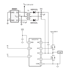
Thank you
Regards,
