This thread has been locked.

If you have a related question, please click the "Ask a related question" button in the top right corner. The newly created question will be automatically linked to this question.

TPS2065D: BVR

Part Number: TPS2065D
Other Parts Discussed in Thread: TPS2052B, TPS2065,

Tool/software:

Hello,

I'm contacting you about a problem we're experiencing with our new design (using a SMARC card): at random, the USB keys we connect to it overheat until they're destroyed (it's no longer possible to recover them afterwards).
It's worth noting that the CPU doesn't seem to be damaged by a destroyed key: when a new key is connected, it works without a hitch.

I'm wondering about the USB power switch. It's the TPS2065DBVR:
It limits the current to 1.5A. However, SMARC recommends using a TPS2052B, which limits current to 0.5A.
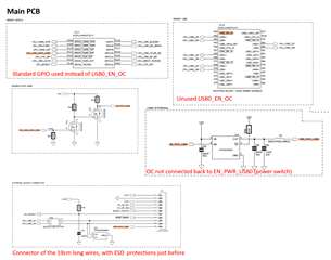
On SMARC recommendations, the USB0_OC output is looped back to the USB0_EN_OC input (called EN_PWR_USB0 on our schematic). This is not the case on our board.
We don't have exactly the same ESD protection as on the recommendations.

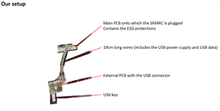
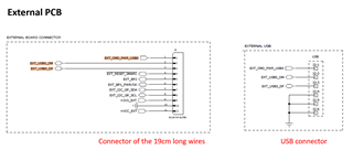
Concerning ESD: the USB is located on a small external board, connected to the main PCB (which contains the SMARC) via wires about 19 cm long. The ESD protectors are located on the main PCB, about 20 cm from the USB connector.

I've attached a photo of the setup showing the two PCBs and the position of the USB, as well as schematics of our two boards and the SMARC recommendations.


Can you think of a reason for the destruction of the USB flash drives? Do you have any recommendations for further development of the PCBs?


Thank you in advance for your help.

  • Hi Teboul,

    Please check the current flowing through the TPS2065D during the fault and capture a waveform of the VIn, Vout and I out. If the current is lower than 1.5A then TPS2065 has nothing to do since it's just a 1.5-A current limiter. I don't think a ESD circuit design can cause a over heat. With more inputs we can check what's causing the issue. I will suggest follow SMARC's recommendations to ensure a reliable operation.

    BR,

    Ke Wang

  • Hi Ke,

    This problem is random. We tried to capture V and I with an oscilloscope, but it's very difficult...

    Is it a problem to use two PCBs separated by a 19 cm long wire?
    Is it better to place the TPS2065 on the USB connector side? This is not currently the case.

  • Hi Teboul,

    Understand and thanks for explaining.

    I don't think a 19 cm cable will be a issue -- if the wire gauge isn't too small it should not cause a huge voltage difference across it. 19 cm is not very long.

    If you think the damage is caused by the OCP level of the TPS2065D, I don't think the location of it matters that much.

    Another thought is that the OCP is a protection, under a fault condition. The root cause of the burnt out is this unexpected fault. With a lower OCP threshold can protect the device from damage but cannot stop the fault happens. Seems the fault itself is not related to TPS2065D, so checking the system and see if there's anything abnormal might be beneficial.

    BR,

    Ke Wang