Tool/software:
Hi everyone,
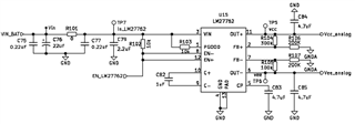
I'm using the LM27762 to generate dual rails of +3V and –2V, each supplying up to 100 mA. The input is a single-cell Li-ion battery, so the input voltage can range from about 4.2V down to something about 3.0V (or less) during discharge.
The LM27762 is damaged (no more +3V and –2V output voltages) when the battery is almost fully discharged. According to the datasheet:
The input voltage range is 2.7V to 5.5V
UVLO kicks in at 2.4V (off) and 2.6V (on)
The negative rail is generated via a charge pump + LDO, which has a dropout voltage of ~30 mV and output resistance of ~2.5Ω at 100 mA
I suspect the problem might be related to insufficient headroom for the negative rail or UVLO triggering, but I’d appreciate any insights from those with experience using this IC.
Has anyone encountered similar behavior with the LM27762?
Any suggestions on how to make the circuit more robust as the battery discharges?
Thanks in advance!