This thread has been locked.

If you have a related question, please click the "Ask a related question" button in the top right corner. The newly created question will be automatically linked to this question.

TPS51200: PGOOD back-powering VIN

Part Number: TPS51200

Tool/software:

Hello. In my application I use VIN=2.5V, and PGOOD pulled up to 3.3V rail, trough 10kOhm resistor. My 3.3V rail is enabled much earlier than the 2.5V.
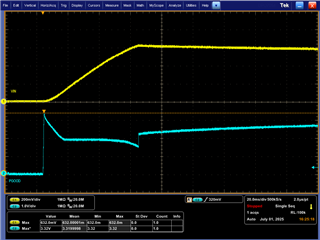
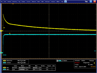
I noticed that my disabled 2.5V rail is back-powered, and charged up to ~620mV from PGOOD pin. Voltage on PGOOD also indicates current being drawn.

I attach a scope screenshot.

Can you please confirm that there is some kind of ESD or clamping circuit between PGOOD and VIN pins? This is not mentioned in datasheet. Absolute maximum rating for PGOOD is 6.5V and recommended max. is 3.5V. 

Thank you,
Rafal

  • Hi Rafal,

    Let me try and confirm this behavior on our EVM first and I'll get back to you. I need to get my hands on a board first so I'll try to get an update on this to you by Friday.

    You're right that I don't see an obvious connection between these two pins from the datasheet block diagram so I'll ask internally about the deeper structure.

    Usually, PGOOD is tied directly to VIN through a 100k resistor.

    Does PGOOD have to be tied to 3.3V external voltage in your case? Does changing to a 100k resistor reduce the VIN charge voltage?

    Regards,

    James

  • Hi James. I made a 10k vs. 100k pullup resistor comparison as you suggested. See the screenshot. The charging is slower, but voltage of charged VIN is not much lower (0.6V vs. 0.45V). 

    My supervisor microcontroller is working on 3V3. In next design loop I will probably reconnect this PGOOD to VIN=2V5 and use a transistor level shifter.
    But just to make sure, I'd be grateful for your confirmation that there is a path between PGOOD and VIN inside the package.


    Thanks,
    Rafal

  • Hi Rafal,

    Thanks for the additional testing. I requested a board so hopefully that comes in tomorrow morning.

    If I get an update on the device internals before the board arrives I'll let you know here. I sent an email requesting a deeper look at the circuit blocks not long ago.

    Regards,

    James

  • Hi Rafal,

    Can you share your schematic with us? I can open a private message space if you would prefer to send the files there. If so, please accept my request.

    There's a simulation we can run to check on this behavior but we need to know the remaining pin connections.

    Regards,

    James

  • Hi Rafal,

    I just received a delivery notification for the TPS51200 board so that should arrive on my desk tomorrow morning. I'll disconnect the default PGOOD resistor from VIN and try biasing it with 3.3V when there's no voltage on VIN to see if I get the same result as you shared above.

    Regards,

    James

  • Hi James. I prefer to not share the schematic. But there is nothing special about it. EN stays low, VIN=2V5 also stays low (or it should be low Slight smile) and PG is pulled up to 3V3 trough 10k resistor. 

    Looking forward to hear about your results. 

    Regards,
    Rafal

  • Hi Rafal,

    This is what I'm seeing on the EVM when I ramp up 3.3V on PGOOD through a 10k resistor.

    This seems to be a direct match to what you see on your end. My VIN charges up a bit higher (632mV)

    Capture 1: Zoom-in on the 3.3V rising action with VIN

    Capture 2: Zoom-out to show the decay of VIN. It takes 100+ seconds for VIN to fully discharge when the pin is floating (input capacitors present)

    Regards,

    James

  • Edit: changed one of the images in my reply above. Posted the wrong one.