Tool/software:
Hello,
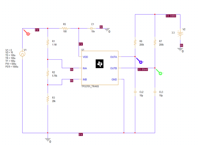
I have been trying to simualte the TPS3701 model on PSpice for TI.
I have followed all the design guidelines as described in the datasheet of this component. Having a VDD of 15V, I would expect my outputs to trigger at 16.5V (OV) and 13.5V(UV).
However when I run the simulation the results I get are not what I expect.
I am not realy sure what I might be doing wrong so any helpt would be appreciated.
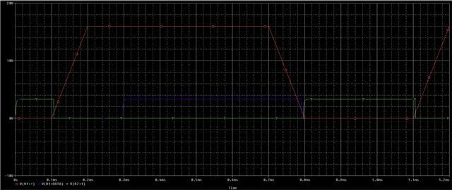
I am attaching a picture of my sschematic and the simulaiton results.
1. Red line represent VDD
2. BLue line represents OUTA
3. Green line represent OUTB
Thanks you in advance,
Kosta Kotsis