This thread has been locked.

If you have a related question, please click the "Ask a related question" button in the top right corner. The newly created question will be automatically linked to this question.

TPSM33625FEVM: TPSM33625FRDNR chipset is dead.

Part Number: TPSM33625FEVM

Tool/software:

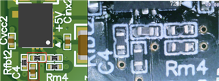
When 24V was applied, the LED turned off for a short time, and then a short circuit occurred in the circuit. After confirming the problem through heat generation, it is presumed that the short circuit occurred in TPSM33625FRDNR, which is responsible for +5V. In fact, when measuring power and GND after the problem occurred, a short circuit occurred.

What could be the problem? No short circuit problem was found in the initial state before power was applied.

Basically, the design itself was based on the evaluation board.

  • Hi,

    It looks like the Mode/Sync pin is directly shorted to VIN. This pin has an ABS MAX rating of 5.5V, which VIN = 24V exceeds.

    If there is an input filter as well, please ensure that appropriate damping capacitor on input is added to ensure that the inductive ring from the input filter is minimized. Please see section 4.4 of this application note for more details on this: https://www.ti.com/lit/an/snva489c/snva489c.pdf

    Thank you,

    Joshua Austria

  • Hello. Thank you for reviewing my circuit.
    While reviewing the PCB, I found that the components were incorrectly attached by the manufacturer.
    C3 and Rfbb1 were swapped, and C4 and Rfbb2 were swapped.

    I think replacing these two components should be a priority.(Biggest Problem)

    Next, I reviewed your feedback.
    I designed it so that I can selectively select FPWM mode and Auto mode by removing/installing Rm1 and Rm3. If the problem is that 24V is applied to the MODE/SYNC pin, it is okay to remove it and use it in Auto mode.

    If I want to use FPWM mode later, I will connect a 76k~220k ohm resistor to the Rm1 and Rm3 positions to create a potential of 2V~5V.

    ++ 

    I will fix the resistor and capacitor swapping issue and I want to remove the problematic parts before retesting.

    Aside from removing Rm1 and Rm3, are there any additional steps I should take, such as removing C3 and C4 / changing Capacity of C3, C4, other Capacitor?

  • Hi,

    Yes the main concern was the Mode/Sync pin receiving a voltage higher than its ABS MAX rating. 

    I believe that resistor/capacitor issue is another likely culprit to the malfunctioning of these parts. 

    As for C3 and C4, those are feedforward capacitors. If you are seeing that your stability is ok with a bode plot, you should not have to change that. 

    Thank you,

    Joshua Austria