This thread has been locked.

If you have a related question, please click the "Ask a related question" button in the top right corner. The newly created question will be automatically linked to this question.

LM317: LDO Regulator Post AC DC Rectifier Ripple but Vout = Vin - Vdrop

Part Number: LM317
Other Parts Discussed in Thread: XTR300, XTR300EVM

Tool/software:

Hi,

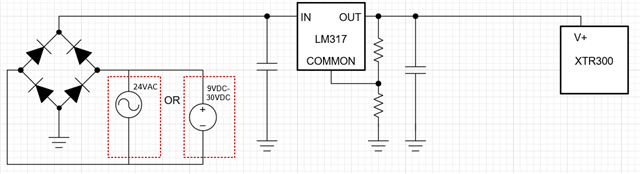
I would like to know if is possible to have a low ripple output to power XTR300, but the Voltage isn't regulated but should be the same Voltage Input afer Graetz Bridge but with very low noise ripple, so this request is because the customer could be power the board with 24 VAC or with 9..30 V DC, so my goal is to have the voltage in V+ XTR300 that depend from the power in.

I hope that my request is clear.

I've found the the LT3081 of Analog Devices could be this, but the simulation not regulated very good.

Thanks

  • Hi Pierpaolo,

    This should be possible. As long as the ripple doesn't bring the device into dropout the LDO should regulate the V+ node at a constant voltage, which is a matter of sizing the LDOs input capacitor correctly.

    Your proposal as I understand it:

    What value/values do you need to V+ to be? Do you want it to select different output voltages to regulate at or to always regulate to the same value.

    Best,

    Gregory Thompson

  • Hi Gregory,

    thanks for your support.

    Il valore V+ depend of the Input Power supply, because the customer could be power the board with range 9...30 V DC or 24 V AC, the current input should be no more 2 A maximum 2,5 A depend of the application if could use all devices communication. So, I need that if the customer use 24 V AC the voltage in V+ should be very low ripple to goal good Vout and stable, maybe 0...10 V with very low ripple. So i mean that if the power in is 12 V DC, the output LDO that power in V+ should be 12 V - Vfdiode and V drop, or if the power in is 15 V DC the same thing and the same with 24 V AC.

    That mean the LDO not regulate the voltage output but filter only the voltage input to reduce the ripple, but I'm not sure if it could be possible.

    Thanks a lot.

  • Hi Pierpaolo,

    There are two ways to do this:

    - Set the output voltage to a value low enough that it never enters dropout over all your operating conditions. The disadvantage here is power dissipation, which may push the device out of its operating region. The ripple here is practically zero, however.

    - Use a tracking LDO and a circuit to determine output voltage dependent on VIN (A tracking LDO simply exposes both sides of the error amplifier to the user so that the output voltage can be determined by the voltage on its ADJ pin). A large enough RC filter should work to filter out the ripple in the AC case and remain constant in DC, and more complex control schemes could have improved performance.

     An RC filter will give you ripple, but it's possible to nearly eliminate it with other control schemes, such as another cheap LDO as a controllable voltage reference or comparators. 

    What level of ripple is sufficient? And what ambient temperature range do you need the end device to operate over? Those questions will determine possibility.

    Best,

    Gregory Thompson 

  • Hi  Gregory,

    thanks for your best support.

    So, I answer your questions:

    - What level of ripple is sufficient? I've supposed about 5 mV, could be better for the XTR300, right?

    - And what ambient temperature range do you need the end device to operate over? The board should be work in industrial ambient, but maybe the temperature could be about from 40 to 50 °C.

    The two ways that you suggest maybe the second could be better, but I've never worked with Tracking LDO, so, I don't know how works.

    Today, I've thought that the solution could be to use an isolated DC/DC converter with 9..36 V DC input and 24 V DC output and then use an LDO to reduce the voltage to 23 V DC more or less to goal very low ripple, so, I know that the consumption will be high, but with this solution I'll have always 24 V DC.

    What do you think?

    thanks.

  • Hi Pierpaolo,

    5mV or less ripple voltage is doable.

    That temperature range should work for a small voltage drop at max load.

    I think that's a good idea. An isolated DC/DC converter like a Buck-Boost converter is a good solution for those values and would work more efficiently than a pure LDO solution. I recommend lowering the DC converter output voltage as possible: power dissipation seems to improve on the XTR300 with lower supply voltages, and you can take advantage of a wider selection of LDOs.

    What's the minimum XTR300 supply voltage that won't interfere with the device's operation?

    Best,

    Gregory Thompson

  • Hi Gregory,

    I thought that could be V+ (24 V DC) and V- (-5 V DC), to use all range in output 20 mA, because maybe the customer could use more devices in daisy chain, so, if I'll power the XTR300 with 15 V DC and - 5V DC? so, i could use also 0..10 V in output right?

    You mean that if I use +15 V DC and -5 V DC the XTR300 dissipate less? I'll have better performance right?

    thanks

  • Hi Pierpaolo,

    You should still be able to use the full 0..10 V range, as the XTR300 seems to require only 3 V headroom (headroom requirement seems symmetric so you wouldn't get much change in performance for the extra 9V of headroom above your output range). Per the XTR300 datasheet most of the power dissipation can be approximated as IOUT*(VS-VOUT), so lowering VS as possible will have better power efficiency:

    The LM1085IT-ADJ/NOPB might be your best option for an LDO here. The part fits the current, voltage, and thermal requirements of your application. 2.5 A * (24 V - 23 V) * 22.7'C/W = 56.75'C rise from ambient, which gives you a maximum ambient temperature of 68.25'C before leaving the parts recommended temperature range at max load. Same equation applies to 16 Vin -> 15 Vout.

    I took a look at our LDO selection and there doesn't seem to be a major difference for voltage range with your current load requirement, and the LDO power dissipation only depends on the voltage drop so the V+ rail voltage isn't a big concern. 

    Best,

    Gregory Thompson

  • Hi Gregory, thanks for your best support.

    So, I ask you:

    - do you mean that if I power V+=5V and V-=-5V, I could obtain 0-10 V in output? 

    - If yes, and I've selected the output current 4-20 mA, the maximum load could be, I think, 150 ohm right?

    - I would like to use V+= 23V and V- = -5V to obtain maximum load possible. The 23V is after LDO from 24V isolated DC/DC. I've tested your evaluation board XTR300EVM rev.A with 24V and -5V and the maximum load is 1100 ohm, sometimes customer use the current loop with other devices, dataloggers or PLCs.

    Waiting your best suggestion.

    thanks

  • Hi Pierpaolo,

    If that's the case, then V+ = 23V is best.

    I meant that you should be able to get the 0..10 V range out of any V+ 15V, and that (as long as you have sufficient headroom) that should be able to source the entire 20mA the way I read the datasheet. e.g:

         V+ = 5V and V- = -5V would give you -2..2 V in output, which does not inlcude 0..10 V

         V+ = 15V and V- = -5V would give you -2..12 V in output, which includes 0..10 V

         V+ = 23V and V- = -5V would give you -2..20 V in output, which includes 0..10 V

    20mA @ 150 Ohms would give you 2V headroom with if the load is grounded, which is smaller than 3V.

    20mA @ 1100Ohms is also 2V headroom with 24V supply.

    With V+ = 23V, I'd expect max load to be 1000 Ohms (20 V across load @ 20mA max output current, 3 V headroom) on any XTR300. However, I can redirect you to the product experts on the XTR300 if you'd like.

    Best,

    Gregory Thompson

  • Hi Gregory,

    thanks, I'll use the DC/DC with 23V DC and -5V, I prefer this solution for customer.

    thanks for your best support. 

    I'll contact you when I'll finish the board so, I could give you a feedback if do you like.

    thanks

  • Hi Pierpaolo,

    Glad I could help. When you finish the board, feel free to start another E2E thread or email me at g-thompson@ti.com for feedback.

    Thanks,

    Gregory Thompson