This thread has been locked.

If you have a related question, please click the "Ask a related question" button in the top right corner. The newly created question will be automatically linked to this question.

TPS6287B30: 2 x TPS6287B30 in Parallel efficiency

Part Number: TPS6287B30

Tool/software:

Hi TI team,

Regarding TPS6287B30 efficiency, I have some questions need your help:

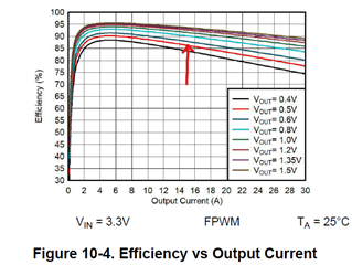
1. From below datasheet diagram, two stacked TPS6287B30 efficiency is only for output 0.8V, could you please provide two stacked TPS6287B30 efficiency curve for output 0.45V or 0.5V? 

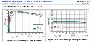
2. In WEBENCH power designer, I could set one TPS6287B30 to simulate efficiency, and how to set two stacked TPS6287B30 to simulate?

Looking forward to your reply.

Thanks

  • Hi Wenkang,

    Thanks for using e2e.

    Please let me check whether we have the data. In case we don't have, would you like me to do a test? If yes, can you pls provide the working condition like Vin, Vout, Iout and inductor type?

    For WEBENCH I'm afraid we don't support stacked mode currently.

    BR,

    Jingyi

  • Hi Jingyi,

    Thanks for your reply.

    Yes, if you have no test data on hand, please help to have a test for two stacked TPS6287B30. Please find below condition:

    1. Vin: 3.13~3.47V

    2.Vout: 0.4~0.6V

    3.Iout: 14~17A

    4.prefer to use Power Choke Inductor for low DCR and better efficiency.

    Thanks

    Wenkang

  • Hi Wenkang,

    Sure. Thanks for the information. Please give me some time.

    BR,

    Jingyi

  • Hi Wenkang,

    Please find the results in the attached picture.

    Test condition: Vin=3.3V, Vout=0.5V, Iout=14~17A, room temperature.

    BR,

    Jingyi

  • Hi Jingyi,

    it looks like I can't find the attached picture in your message, not sure if you have successed to upload picture already.

    please help to send again.

    Thanks

    Wenkang

  • Hi Wenkang,

    Oh I'm sorry. Looks like something went wrong. 

    Can you see the attachment this time? The blue line is the data I got manually, and the orange line is the approximate efficiency.

    Thank you and best regards,

    Jingyi

  • Hi Jingyi,

    Yes. I have got your test data. Thanks for that.

    And from single device efficiency figure,I am not sure how much the efficiency of the two stacked devices improves compared to a single device at 15A load.

    In additonal, I guess the swtiching frequency is 1.5Mhz for both two stacked devices, am I right? How about the output voltage ripple?What inductor do you use for this test data?

    It will be appreciate for your support.

    Thanks

    Wenkang

  • Hi Wenkang,

    I'm deeply sorry that the previous efficiency curve is with a 2.5MHz switching frequency. 

    Here is the efficiency results with 1.5MHz. Other working conditions remain the same. The inductor is the default one on our EVM, 744302010 Wurth Electronik.

    The output ripple is expected to decrease a bit compared to the single version, but not very significant.

    BR,

    Jingyi

  • Hi Jingyi,

    It doesn't matter. Thanks for your test data.It looks efficiency with 1.5Mhz is 2% more than 2.5Mhz's.

    The inductor on your EVM is too tall to use for us, could you please replace with XGL4012-101MEC, then take a test? If it's difficult to replace the inductor manually, I am not sure if possible to simulate efficiency with XGL4012-101MEC.

    And the last, would you please help to measure efficiency curve at output 0.45V?  

    The test condition:Vin=3.3V, Vout=0.45V, Iout=14~17A, room temperature.

    Thank you very much.

    Wenkang

  • Hi Wenkang,

    Of course. Please give me some time to get this inductor.

    Thank you and best regards,

    Jingyi

  • Hi Wenkang,

    Thank you very much for your patience. 

    Unfortunately there's been some trouble to get the inductor XGL4012-101MEC, and we don't know how long we still need to wait. Therefore I used another inductor XEL4020-101ME to run a test first.

    The result is as follow:

    Based on the above inductor's DCR and working condition, the efficiency using XGL4012-101MEC is expected to be around 1% less.

    I will keep waiting for the inductor to arrive.

    Thank you and best regards,

    Jingyi

  • Hi Jingyi,

    Thanks for your test data.

    I think new efficiency curve with XEL4020-101ME is very valuable. When you have XGL4012-101MEC, Please help to measure efficiency again, it's not very urgent now.

    How about output voltage ripple with XEL4020-101ME, I am not sure if you could have ripple tested or you could simulate.

    Thanks again,

    Wenkang

  • Hi Wenkang,

    Thanks. I will test it as soon as I get the inductor.

    For the ripple I can run simulations. The SIMPLIS model is used for simulation, with Vin=3.3V, Vout=0.45V, Iout=17A, Co=4x47uF+3x100uF. 

    The Vout ripples are expected to be similar, as shown in the simulation results. It depends more on the Cout capacitance and ESR.

    Single:

    Two in stack:

    BR,

    Jingyi

  • Hi Wenkang,

    Thank you very much for your patience. I finally got the samples.

    Please find the efficiency with inductor XGL4012-101MEC, Vin=3.3V, Vo=0.45V, Io=14~17A.

    Thank you and best regards,

    Jingyi

  • Hi Jingyi,

    Really appreciate for your work.

    I think I don't have any other questions about this material for now.

    Thanks Again!

    Wenkang