Other Parts Discussed in Thread: LM70880
Tool/software:
Dear TI experts,
My customer did EMC test of their product using LM70880-Q1.
In that test, wide range of frequency (from 40MHz to 150MHz) fail situation is observed. Please see the file below ;
And my customer have a question to improve this EMC situation.
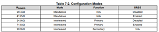
1) In section 6.3.6 of datasheet, I can see Dual Random Spread Spectrum.
It seems that 41.2Kohm is effective for 150KHz~30MHz, 71.5Kohm is effecttive for 30MHz~108MHz.
1-1) Do you have any special reason for this resistor value? (formula, equation, etc..)
1-2) Should I use only between these 2 values? or can I use other values for specific frequency? (for example, 40MHz~150MHz)
2) About CBOOT pin, My customer added additional 1ohm because Vin is 7V.
2-1) Is there any possibility of resonance in the device because of 1ohm external resistor?
2-2) Can my customer remove 1ohm resistor if Vin is 7V?
3) About BIAS pin, My customer connected it to GND based on EVM schematic and WEBENCH.
But datasheet says that there are some options for BIAS pin.
Is there any example for reducing EMC using this BIAS pin?
Please check this issue. Thanks.
Best regards,
Chase