This thread has been locked.

If you have a related question, please click the "Ask a related question" button in the top right corner. The newly created question will be automatically linked to this question.

BQ25751EVM: Unable To Switch From Input Power To Battery Power While Drawing Current From Vsys

Part Number: BQ25751EVM
Other Parts Discussed in Thread: BQ25750, LM74930, BQ25751

Tool/software:

Good morning everyone,

I am currently experiencing a strange problem while testing out a BQ25751EVM, and would like some suggestions on how to fix the behavior. Please let me know if you require any additional measurements, or information about the test setup.

The problem is as follows:

  1. The board is able to charge the battery as well as supply power to a load from a power supply connected to VAC (J1 on the board).
  2. If the power supply at VAC is off, then current will flow from the battery to the load on VSYS via BATFET (Q7,Q8), provided the load is connected after BATFET becomes active.
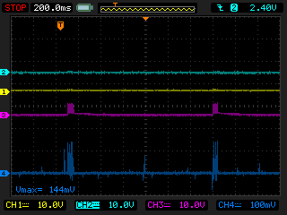
  3. However, if the battery and load are being charged from VAC, and the power from VAC is either turned off or disconnected, the system will end up in an invalid state. The system will repeatedly pulse BATFET for 10 cycles, then turn off entirely for a full second before trying again.
  4. Reconnecting VAC if the board is in this state does not result in the board resuming it's initial state. The only way to return to a regular state is to disconnect and then reconnect the load.

Below is the waveforms of the behavior: Channel 4 is connected to a current clamp that is monitoring the current flowing out of the battery. It's sensitivity is 10mV/A. Channel 3 is connected to BATDRV, Channel 2 is VAC, and Channel 1 is connected to the output.

The first waveforms are of the periodic current spikes observed. If the readings on channel 4 are to be believed, these spikes are up to 16A in magnitude.

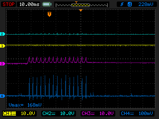
The exact spacing between pulses is 3.2ms.

Conditions needed to reproduce the behavior:

You must have a load connected to VAC that is consuming more than some amount of current. The amount of current draw required to reproduce the error is inconsistent and can change. However the lowest I have seen this current value is 270mA, and the highest I have seen is 3.8A. The behavior starts once the load is either disconnected or unplugged.

Test Setup Details:

There have been several modifications made to the eval board so that it matches with the design of a circuit we are validating. These are summarized in the table below:

Designator

Function

Old Component

New Component

Footprint

R34

Expand Temp Range

5.23kΩ

6.49kΩ

0603

R65

Expand Temp Range

30.1kΩ

20kΩ

0603

R67

ICHG

4.99kΩ

13.8kΩ

0603

R66

ILIM_HIZ

2.49kΩ

2kΩ

0603

R21

ACUV

1MΩ

0Ω

0805

R27

OV/UV prot


DNP

0805

R30

ACOV

25.2kΩ

0Ω

0805

R28

 Set FB for 24V system

249kΩ

100kΩ

0805

R64

Set FB for 24V system

13.7kΩ

6.8kΩ

0805

R2

AC Current Sense

2mΩ

1mΩ

2512

  • The load being used on VSYS is a Korad KEL103 electronic load. The test conditions were repeated using resistors instead of the electronic load, and no effect was had on the behavior of the device.
  • Switching Power is being provided from an external 5V power supply. It can also be tied to VREG, as this has no effect on the behavior.
  • JP1, JP4, JP5, JP6, JP9,JP10, JP12 (2-3), JP13,JP14,JP15, and JP16 are all bridged
  • The power supply voltage on VAC is 25V.
  • A 24V Sealed lead acid battery is connected to V_out

Additional Information I have Gathered:

  • Measuring the gate of all the buck-boost converter's switching elements (HIDRV1,HIDRV2,LODRV1,LODRV2) shows that they all remain at 0 volts when the board is in it's invalid state.
  • Reading the fault status and fault flag registers when the board is in it's error state shows no faults
  • Reverse mode and auto-reverse mode still behave as expected, the only problem is with the BATFET activation
  • Providing switching power from either an external source or VREG has no effect on the behavior observed.
  • Hello Byron,

    Can you provide a register dump of when this issue is occuring?

    Best Regards,

    Christian.

  • Hello Christian,

    Here is a dump of the registers during its error state:
    Register 0x0000: 0x0010
    Register 0x0002: 0x0640
    Register 0x0006: 0x0640
    Register 0x0008: 0x0348
    Register 0x000A: 0x0640
    Register 0x000C: 0x03E8
    Register 0x0012: 0x00A0
    Register 0x0014: 0x0008
    Register 0x0015: 0x0010
    Register 0x0016: 0x00D5
    Register 0x0017: 0x0009
    Register 0x0018: 0x00C0
    Register 0x0019: 0x0000
    Register 0x001A: 0x0020
    Register 0x001B: 0x0082
    Register 0x001C: 0x0081
    Register 0x001D: 0x0040
    Register 0x001E: 0x0000
    Register 0x001F: 0x0000
    Register 0x0021: 0x0088
    Register 0x0022: 0x0000
    Register 0x0023: 0x0000
    Register 0x0024: 0x0000
    Register 0x0025: 0x00E9
    Register 0x0026: 0x00E0
    Register 0x0027: 0x0000
    Register 0x0028: 0x0000
    Register 0x0029: 0x0000
    Register 0x002A: 0x0000
    Register 0x002B: 0x0060
    Register 0x002C: 0x0002
    Register 0x002D: 0x05D5
    Register 0x002F: 0x01F2
    Register 0x0031: 0x2EC9
    Register 0x0033: 0x31A8
    Register 0x0035: 0x2F4D
    Register 0x0037: 0x01FE
    Register 0x0039: 0x0000
    Register 0x003B: 0x0000
    Register 0x003C: 0x0000
    Register 0x003D: 0x000A
    Register 0x0062: 0x0002
    Register 0x0000: 0x0002
    Register 0x0000: 0x0002

  • Hello Bryon,

    I'm reviewing your register data, and will provide an update after I gather more information.

    Best Regards,

    Christian.

  • Hello Bryon,

    Thank you for your patiance, I have a few suggestions and questions:

    • R28 should be 249kohm, R64 should be the only resistor changed to change the VFB voltage.
    • What value are you trying to set ACOV and ACUV?

    Best Regards,

    Christian.

  • Good Morning Christian,

    I actually have a few updates regarding the problems we are currently facing with the BQ25751EVM.

    The first is that we have purchased a second BQ25751EVM, which we left on factory default configuration, and experienced the exact same issues switching under load described in my previous post. I read through a BQ25750 schematic checklist that was linked in another post on this forum, and saw that R28 needs to be 249kΩ. However because of the fact that the issues were also present with an unmodified evaluation board, I am skeptical that this is the primary cause of the problems we are seeing. Regardless, we will be making the change back to having R28 be 249kΩ, and see if there is any effect.

    The values for ACOV and ACUV were set to 4 and 60V, as in our use case there is an LM74930 ideal diode controller upstream which provides the protection for the circuit. However, we have continued testing the circuit, and realized that we had made a design oversight with regards to setting the voltage at which the controller transitions to Hi-Z mode via the ACUV pin.

    Note that the ideal diode was not present in the test setup, and we instead relied on the voltage limits of our power supply.

    Subsequently, we have replaced R21 with an 887kΩ resistor, and R27 with a 127kΩ resistor. This sets the UV threshold for the system at 8.78V. Once again, we have left ACOV tied to ground, as the circuit is protected upstream by the ideal diode controller. Making this change, however, did not solve the problem with the transition from external power supply to battery power.

    This afternoon I will try populating the snubber circuitry on the board (D7, R14, R15, C14, C15) and see if that has any effect.

    In addition, we started looking for ways to maintain power supply even if the transition directly from charging to Hi-Z mode doesn't work. We found that we can configure the BQ25751 to transition to auto-reverse mode by enabling the EN_AUTO_REV bits, then monitor for the interrupt pulse triggered by the transition into reverse mode. Once we detect the transition into reverse mode, we set the EN_HIZ bit after a short time delay to force the device into Hi-Z mode. Doing this results in a successful transition into HI_Z mode even if under load.

    Here is an oscilloscope transition of the process.

    CH1 is the /INT pulse, CH2 is the voltage at VSYS CH3 is the voltage at the BATDRV test point, CH4 is the current out of the battery with a 10mV/A sensitivity. The time delay between the /int pulse and the setting of the EN_HIZ bit is 50ms. We still see some strange cycling behavior, however eventually it settles into Hi-Z mode.

  • Hello Byron,

    This seems related to the powerpath switch over. We have seen this issue on previous BQ2575x device

    We have an FAQ explaining why this issue is occuring and potential work arounds.

    Please refer to this E2E post:https://e2e.ti.com/support/power-management-group/power-management/f/power-management-forum/1391181/faq-bq25750-what-do-i-need-to-know-about-the-bq25750-power-path-switchover

    Best Regards,

    Christian