


Tool/software:
Hi,
I have a 600W PFC, running from aircraft 400Hz, 115V AC - generating 400V DC for an LLC stage.
If I disable phase B (tying PHB high) , it works very nicely in single phase mode up, delivering up to about 270W before it hits the max on time of the FETs.
When I enable phase B, again it works fine, in interleaved mode, until we get to about 230W, when I observe a solitary half-width 'on' pulse on GDA, the same time/voltage level after the zero-cross point, which then puts the two channels into phase with each other. They then remain in phase for the majority of the duration of the half-cycle before dropping back into interleaved mode at about the same time/voltage before the next zero-cross.
Obviously when the two channels are in-phase, the total current is much higher than it should be when they are working out of phase.
I've monitored the COMP and ZCDx lines and don't see anything around the point of change. I'm fairly sure it's not spurious noise as it's so consistent - every half cycle is the same and the 'glitch' occurs at exactly the same point every time.
If I vary the load, the percentage of the half-cycle which is in phase (out of interleave) changes. Likewise, if I change the input voltage, it changes.
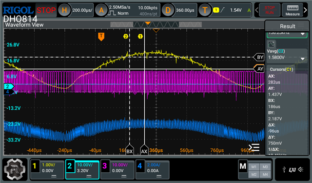
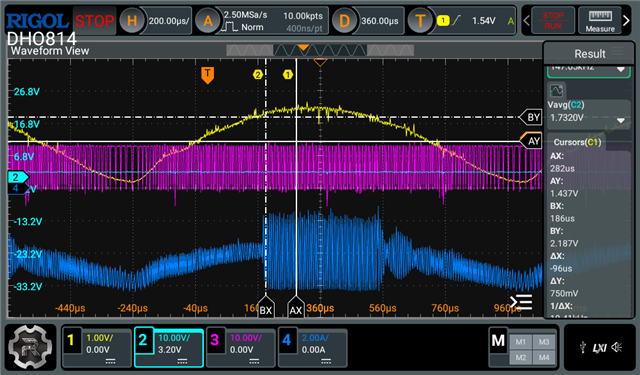
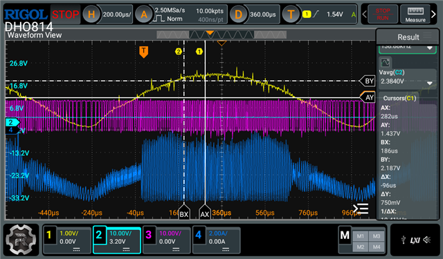
These images (different loads) show VINAC (yellow), COMP (cyan) - difficult to see against the pink, but value measured on the right, GDA (pink) and AC current (blue).
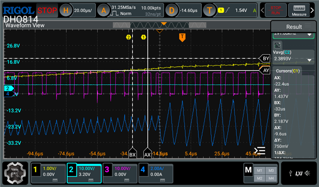
Here is a zoom-in on the transition. You can see, just to the right of the cursors, that we get a short on-pulse on GDA and following this GDA and GDB run 100% in phase for the remainder of the cycle until the input voltage drops to the same level. It isn't shown, but I monitored ZCDA and ZCDB around this point, and we get a normal pulse at the end of each on-pulse.
What could be causing this, or what else can I tell you or measure to help you diagnose what's going on here?
My inductor is 225uH (Wurth 760805410), Fet: IPL60R085P7, Diode: TRS4V65H, Rcs shorted out.
TIA - Tom.
