This thread has been locked.

If you have a related question, please click the "Ask a related question" button in the top right corner. The newly created question will be automatically linked to this question.

TPS6594-Q1: TPS6594EVK

Part Number: TPS6594-Q1

Tool/software:

Hi ,

I'm working with TPS6594 pmic and Arduino due controller to I2C read function with CRC and without CRC ,

my goal was to check if received CRC and calculated CRC are correct then compare further write next data.

but current with my code i'm receiving CRC (0x3A) while calculated CRC( 0x9F) for data for read with CRC is { 0x90, 0x1, 0x91 , 0x82}.

i have attached snippet of code for read operation with CRC and CRC calculation method.

help me to fix this code.
 

#include <Wire.h>

#define TPS6593_ADDR 0x48  // Default 7-bit I2C address

const uint8_t CRC_POLY = 0x07;
const uint8_t CRC_INIT = 0xFF;
const uint8_t INIT_ADD = 0x01;

// Calculate CRC-8 over data array
uint8_t calculateCRC(const uint8_t *data, uint8_t len) {
  uint8_t crc = CRC_INIT;
  for (uint8_t i = 0; i < len; i++) {
    crc ^= data[i];
    for (uint8_t bit = 0; bit < 8; bit++) {
      if (crc & 0x80)
        crc = (crc << 1) ^ 0x07; //crc = (crc << 1) ^ CRC_POLY;
      else
        crc <<= 1;
    }
  }
  return crc;
}

// Read registers with CRC verification
bool readRegistersWithCRC(uint8_t startReg, uint8_t *buffer, uint8_t length) {
  if (length == 0 || buffer == NULL) {
    Serial.println("Invalid parameters for readRegistersWithCRC");
    return false;
  }

  // Send start register address + CRC
  uint8_t addrCRC = calculateCRC(&startReg, 1);
  Wire.beginTransmission(TPS6593_ADDR);
  Wire.write(addrCRC);
  if (Wire.endTransmission(false) != 0) {  // repeated start
    Serial.println("I2C error on address write (with CRC)");
    return false;
  }

  // Request 2 * length bytes (data + CRC pairs)
  
  Wire.beginTransmission(TPS6593_ADDR);
  Wire.write(startReg);
  Wire.requestFrom(TPS6593_ADDR, (uint8_t)(length * 2));

  const uint8_t i2c_id_w = (TPS6593_ADDR << 1) ; // 7-bit addr + W
  const uint8_t i2c_id_r = (TPS6593_ADDR << 1) | 1; // 7-bit addr + R
  const unsigned long timeoutMs = 100;

  for (uint8_t i = 0; i < length; i++) {
    unsigned long startTime = millis();
    while (Wire.available() < 2) {
      if (millis() - startTime > timeoutMs) {
        Serial.println("Timeout waiting for data+CRC (with CRC)");
        return false;
      }
      delay(1);
    }
    uint8_t data = Wire.read();
    uint8_t recvCRC = Wire.read();
    
    Serial.print("data at reg 0x");
    Serial.println(data, HEX);

    uint8_t reg = startReg + i;
    uint8_t crcInput[4] = {i2c_id_w, reg, i2c_id_r, data};
    Serial.println();
    uint8_t calcCRC = calculateCRC(crcInput, 4);

    if (recvCRC != calcCRC) {
      Serial.print("CRC mismatch at reg 0x");
      Serial.print(reg, HEX);
      Serial.print(": received 0x");
      Serial.print(recvCRC, HEX);
      Serial.print(", calculated 0x");
      Serial.println(calcCRC, HEX);
      return false;
    }
    buffer[i] = data;
  }
  return true;
}

  • Hi Suhas,

    Please check attached document to test your code. These are write/read examples with CRC. 

    One note, for reading repeated start must be used in between.

    By the way, have you enabled CRC in first place? Looks like you're receiving maybe next register data by doing  { 0x90, 0x1, 0x91 , 0x82} if this is reading register 0x1 data.

    Which OPN TPS6594-Q1 you're trying to connect?  

    Br, Jari

  • Hi Jari,

    OPN : TPS6594133ARWERQ ,

    i'm not able to find test code , could re-share it.

    not sure but it enabled , to confirm that how can i read I2C1_CRC_EN

    The I2C target device (i.e. the TPS6594-Q1) provides T_CRC[7:0], which is calculated from the I2C_ID, W, ADDR, I2C_ID, R, and the RDATA bits (32 bits).  as per Fig 8.62 (datasheet)

    as device id : 0x48 , above data can be represented as {i2c_id_w, reg, i2c_id_r, data}  = { 0x90, 0x1, 0x91 , 0x82}.

    best regards,

    Suhas

  • Hi Suhas,

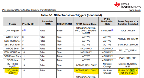
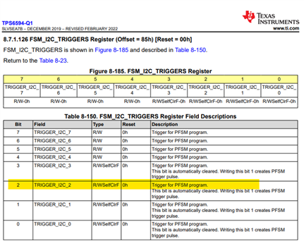
    Before trying CRC communication have you written I2C2_TRIGGER high in ACTIVE or MCU_ONLY mode? 

    After above you can check if I2C1 and I2C2 CRC is activated by reading register 0x11a. This is in address I2C1 0x49. If register value is 0x06 then CRC is enabled.

    Attaching file again. There is no code but info how to confirm correct CRC data.

    /cfs-file/__key/communityserver-discussions-components-files/196/I2C_5F00_CRC_5F00_enabled_5F00_examples.docx

    Br, Jari

  • Hi Jari ,

    i captured log of both I2C 1&2 but didn't see this address 0x11a , current my i2c1 address is 0x48 , I2c2 address is 0x12. (as per default NVM config)
    below is frame which is received from :  write to 0x12 ack data: 0x05 0x0C
     i'm expecting this is setting for CRC.

    one more thing i observed :  does that means by default in NVM , CRC is enabled ?

  • Hi Suhas,

    To access register 0x11a you will need to use I2C1 address 0x49. So it register 0x1a under address 0x49.

    To enable communication CRC you will ne write to following bit.

    REG_CRC_EN is different from communication CRC. This register CRC protects only registers data against bit flip.

    Br, Jari

  • HI Jari ,
    i went to reading these register and found these in response
    as i read 5 register from address 0x49 starting from 0x19 

    write to 0x49 ack data: 0x19
    read to 0x49 ack data: 0x80 0x00 0x0B 0x16 0x88  

    based on that 0x1A data is 0x00  does that mean its CRC is disabled .

    then one more doubt is is 0x3A TCRC ? reference to this
    as device id : 0x48 , above data can be represented as {i2c_id_w, reg, i2c_id_r, data}  = { 0x90, 0x1, 0x91 , 0x82}.

  • Hi Suhas,

    Yes, it means CRC for communication is not enabled. 

    Have you written 0x1 to TRIGGER_I2C_2 first? 

    Based on your scope shot you are just receiving next registers data.

    Br, Jari

  • Thanks Jari ,

    for helping out further i will check other thing .