This thread has been locked.

If you have a related question, please click the "Ask a related question" button in the top right corner. The newly created question will be automatically linked to this question.

UCC21551-Q1: Application question for negative bias

Part Number: UCC21551-Q1
Other Parts Discussed in Thread: TINA-TI

Tool/software:

Hi expert, 

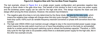
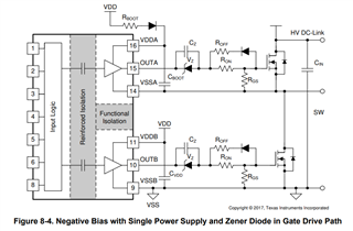
There have an example in datasheet for application circuit with negative bias, see below. 

I am not quite understand why it says determine by duty cycle? Need your help to explain here. 

Thanks!

Ethan Wen

  • Hi Ethan,

    This application circuit shows an AC coupled output, which is biased negative by a Zener diode. Therefore, the output voltages are not very stable, and their absolute values depend on the current through the Zener diode, which is proportional to the output duty cycle.

    Absolute output voltages also depend on the initial condition of Cz. Below is a TINA-TI simulation file you can use to investigate. 

    3343.bootstrap_circuit_negative_turnoff.TSC

    The main problem with this circuit is that if you set Cz too large, it will take time to charge, and this can expose the gate to overvoltage at startup. If you set the capacitor too small, it forms a capacitor divider against the input gate capacitance, and you have attenuated AC output voltage range.

    You may end up needing to use an isolated power supply if you need a negative turn-off voltage.

    Best regards,

    Sean