This thread has been locked.

If you have a related question, please click the "Ask a related question" button in the top right corner. The newly created question will be automatically linked to this question.

BQ25628E: Via sizing in PCB layout

Part Number: BQ25628E

Tool/software:

Hi;

(Apologies that this question has to do more with manufacturing rather than technical specs - I'm in the learning phase with this IC). 

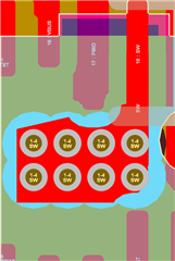
I am trying to develop a design using the BQ25628E. In the datasheet for this part, the PCB Layout guidelines specify using "many vias" in the path from the SW pin through CBTST and out to the inductor. The guidelines illustrate what seem to be very small vias here (0.1mm? 0.15mm?), which seem to be on the 'difficult' end of the manufacturing spectrum (at least, when referring to capabilities listed by JLCPCB and similar manufacturers' websites). 

I'm curious if larger vias may be used here, or if any elaboration might be made on the manufacturability of these vias? I get a lot of DFM errors about annulus spacing when trying to fab a board using this part, and I'm curious if there's particular language I should use in conversation with a manufacturer about these, or any general tips for success having a board made with these tiny fellas. 

Thank you!

  • Hi,

    I believe the VIAs you are referring to are the ones placed directly under the center of the IC which are used to route the SW node under the IC, through the PCB, and back out to an inductor on the EVM. The hole size for these vias are 6 mil (1.5mm) and they are on the smaller side. They do require plating and in our EVM they are tented. Additionally they are connected to a small metal plane so the minimum annular ring isn't as relevant to the manufacturing, the plane should spread wider than the minimum annular ring distance any ways:


    Unfortunately with regards to the specifics on manufacturability, you will have to consult with your manufacturer on their capabilities. I was not involved with the manufacturing of the boards so I don't have any particular language when speaking with the manufacturer. In terms of using larger vias, that shouldn't be an issue. The idea ultimately is to minimize the resistive path between the SW and the Inductor, SW and the CBTST, and the inductor and SYS. 

    Best Regards,

    Juan Ospina

  • Thank you so much; yes, these are the exact vias to which I'm referring. It's fantastic to know I could just size them up, though (in the interest of learning) I am curious if another thing I could do is remove the annular ring on interior layer(s) that have no connections - I think the DFM errors I am seeing are about the space between (internal, unconnected) annular rings, which I *think* are sort of irrelevant and could be safely removed? 

    (I have not yet designed something requiring the precision this device requires, so am still learning my way around how to design for it)

    In any case, it's great to understand all this better, thank you!

  • If there is no routing in the middle layers then I believe they can be removed without issue. I would confirm that doesn't pose an issue on the manufacturer's side.

    Best Regards,
    Juan Ospina