This thread has been locked.

If you have a related question, please click the "Ask a related question" button in the top right corner. The newly created question will be automatically linked to this question.

LMR14203: Inverted / negative Output possible?

Part Number: LMR14203
Other Parts Discussed in Thread: REF35, REF2033

Tool/software:

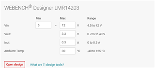
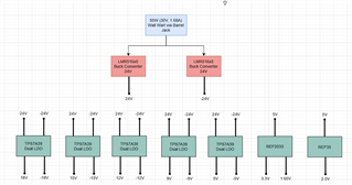
I am looking to have a negative Vout using the LMR14203. I am looking to step down 30V at Vin to -5V at Vout. I tried using the power designer tool to create a topology for me, but it didn't allow output ranges in the negatives. Is there some work around regarding the external circuitry that would allow me to see -5V at the output? 

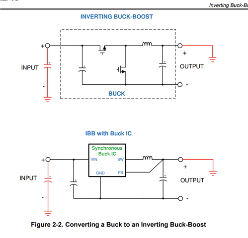
Does following something like the schematic below work for this device for obtaining a negative Vout?

  • Hello Justin

    30 to -5V would be possible using this device, only concern is there is not enough margin for Vin swing. For this application you would device which supports Vin > Max input voltage + |-Vout|. If long cables are used to power up the device, Vin seen by the device could exceed recommended operating max. 

    Additionally, WEBENCH design of this device doesn't support Vout below 0.765V

    I would recommend using PSPICE for TI here. You can refer simulation section of same app note for work around

    Let me know max load current in your application to check if this device could support that.

    Thank you

    Regards

    Onkar Bhakare

  • Ok I didn't catch the fact that Vin > Max input voltage + |-Vout| for a negative output configuration of a buck converter.

    For my system I am building a power board and I am in need of a -24V clean power supply rail. My board will be supplied by a 30V, 1.68A (50W) supply via a wall wart. Thus, the largest range I would have would be 30V in and -24V out meaning Vin for the buck converter should be at least 58V, correct me if I'm wrong.

    Is there any particular device that can do 30V Vin and -24V at Vout. I also need as low noise as possible (ripple, p-to-p, etc).

    Particularly, Im looking at something like the LMR516x5 that can go up to 63V. It has low output voltage ripple. Can a 30V in to -24V out be done for this device? Are there any possible issues? 

  • Yes Justin

    Particularly, Im looking at something like the LMR516x5 that can go up to 63V. It has low output voltage ripple. Can a 30V in to -24V out be done for this device?

    That should be possible. Note even though you load current is 1.68 A. You would need 3.5A variant of LMR516x5 family. In IBB load current and inductor current has following relation. Ultimately inductor current would flow through the device.

    Check out section 4.2 Current Stress from Working with Inverting Buck-Boost Converters (Rev. B)

    Could you please share what is minimum Vin, you want it to support and max current load that Min Vin.

    Thank you

    Regards

    Onkar Bhakare 

  • I plan on creating a board like so:

    I want to use the bucks to create +- 24V rails that can be used as the supplies to LDOs that can produce various voltage supply rails. Particularly, the loads that will attach to the supply rails (output of LDOs) are going to typically consume less than 50mA. Additionally, the LDO that supplies 5V will also be used as Vin to the REF2033 and REF35 (which consume <= 20mA each).

    The current capability of the TPS739 is 150mA but in my use case, devices that will connect to the supply rails won't use that much and will consume at most at around 50mA. For the max current load, it depends on how many devices are connected to the rails and how much current those device are going to consume at most. 

    The IBB would be the LMR516x5 that produces a -24V rail

  • Hello Justin 

    Thanks for sharing this! 

    How many devices you plan to put on -24V rail? Evaluate current stress on the device accordingly as discussed in the section 4.2

    Thank you

    Regards 

    Onkar Bhakare

  • Hello Justin 

    Let me know if need further help

    Thank you

    Regards

    Onkar Bhakare