This thread has been locked.

If you have a related question, please click the "Ask a related question" button in the top right corner. The newly created question will be automatically linked to this question.

UCC23514: Drive Strength

Part Number: UCC23514
Other Parts Discussed in Thread: UCC23513, UCC23525

Tool/software:

Hi Team,

Could you please help provide the how to formula of calculating the drive strength need for SiC MOSFET paired with UCC23514? 

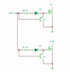
Customer would like to use UCC23514 with 2-FETs or 3-FETs, and cannot accept external BJTs due to size issue.

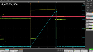
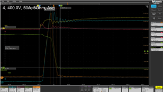
The system conditions are: 54kHz fsw, 5.1ohm Rg-on and 2.55 Rg-off, Ciss 2.54nF, Qg 63.4nC, Eon 282uJ.

Any further questions please feel free to contact me, thanks in advance.

BTW, do we have larger drive strength device which is similar to UCC23514? Customer don't need DESAT function.

BRs,

Francis

  • Hi Francis,

    The best way to analyze drive strength's effect on switching is with a double pulse test. For a single turn-off and turn-on cycle, you can measure the switch's Eon/Eoff at a specific Vds and Id. You can use this measured Eon/Eoff, plus conduction losses, to estimate an operating thermal power of the FET.

    The losses will decrease for higher drive strength (lower gate driver Roh). If the losses are acceptable, you may also see if there is significant switch node ringing. This can cause damage to the FET, and often customers will add gate resistance to decrease drive strength to decrease ringing. You can fine tune this external Rg to reduce Vds ringing while trying not to increase Eon too much.

    In the case of the UCC23514, I have already measured it many times with double pulse tests. I have not used it to drive several parallel FETs, but this will have the effect of the current to be shared between each of the driven gates. If the drive strength is lower, it is the same effect as using a gate resistor to limit the current from one gate driver into one FET. 

    Double Pulse test example with UCC23513, Rg=5 Ohms

    CH1= Vgs

    CH2=Id

    CH3=Igate

    CH4= Vds

    Eon Measurement:

    The key problem with parallel FETs is that you should not short their gates together. This will cause internecine oscillation during switching, due to unequal Vth. With a single output, this can be achieved by using a large enough gate resistor from the output to each device's gate.

    If you want to have a Miller clamp, then a better method is to use a local PNP strong turn-off for each device, since this will keep the gates isolated: 

    Since you cannot really use an internal Miller clamp for parallel FETs, you can consider the UCC23525. This is an updated version of the UCC23513, and it will have a stronger drive strength for external gate resistors lower than 12 ohms. For larger external gate resistors, UCC23513 is still the best choice for higher drive strength.

    Best regards,

    Sean