A related question is a question created from another question. When the related question is created, it will be automatically linked to the original question.
If you have a related question, please click the "Ask a related question" button in the top right corner. The newly created question will be automatically linked to this question.
Part Number: LM5176-Q1 Other Parts Discussed in Thread: LM5176
Tool/software:
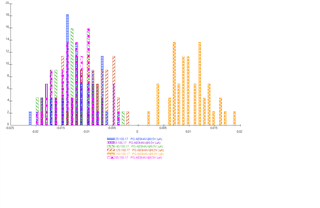
The leakage at PGOOD is 0.1mA, which is significant when it's about reducing the standby. Knowing this is a worst case value, please give a supporting graph to estimate the applicable value.
Hi Stefan, I didn't quite catch what the x-axis data is. I'm looking for the current at 25, and 110 degC, let me know if u have any specific data on this.
x Axis is the the measured leakage. y-Axis is the amount of devices where this leakage as been measured. Colour and pattern marks the Temperature. BIAS was 8.5V.
the BIAS voltage in this context is the voltage applied on PGOOD (so the BIAS voltage of that Pin) - not the voltage on the BIAS pin of the LM5176. Sorry for the confusion.
I do not understand what you would like to ask with that statement: "And with number of devices, the average is considered?"
Stefan, I see I've made a mistake in the conversion, although I don't usually :) The 100nA get converted to 0.1uA not mA as I have incorrectly mentioned at the starting of this chain. Forgive me for taking up ur time, yes,I got to know better about the parameter and that helps. Thank u for assisting.