This thread has been locked.

If you have a related question, please click the "Ask a related question" button in the top right corner. The newly created question will be automatically linked to this question.

TPS552892: not stable

Part Number: TPS552892

Tool/software:

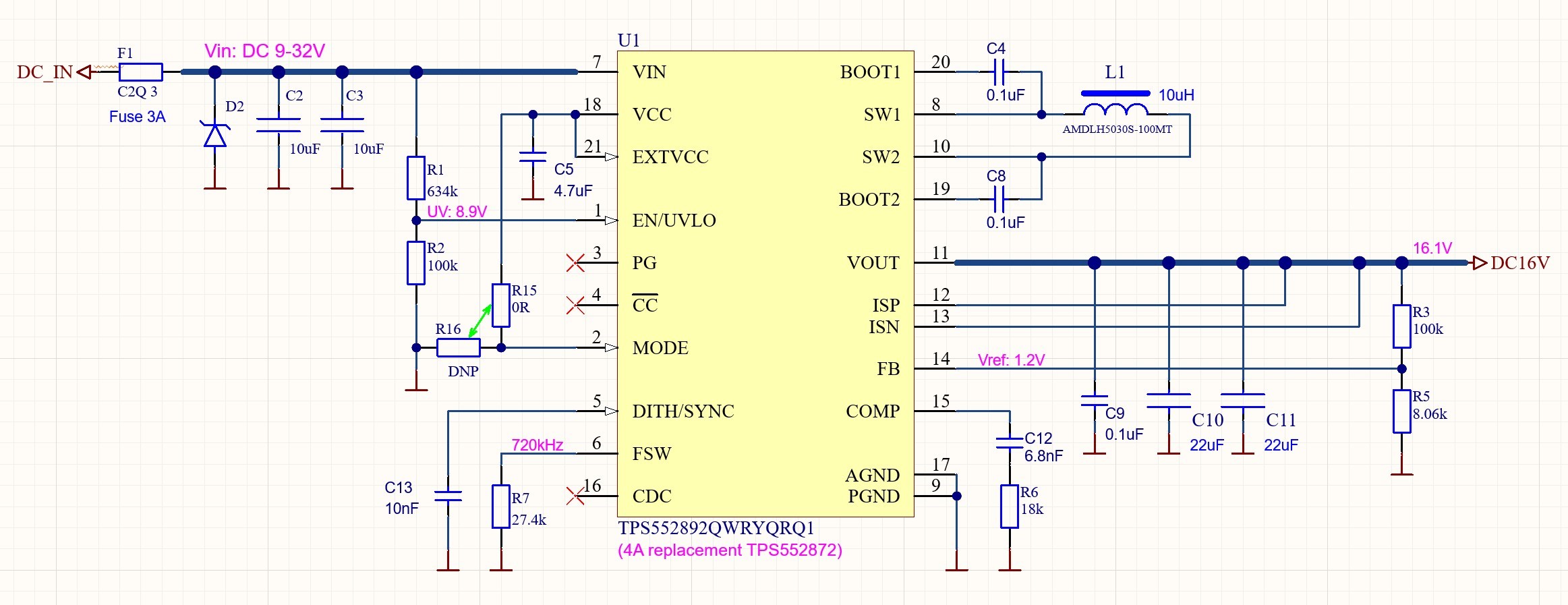
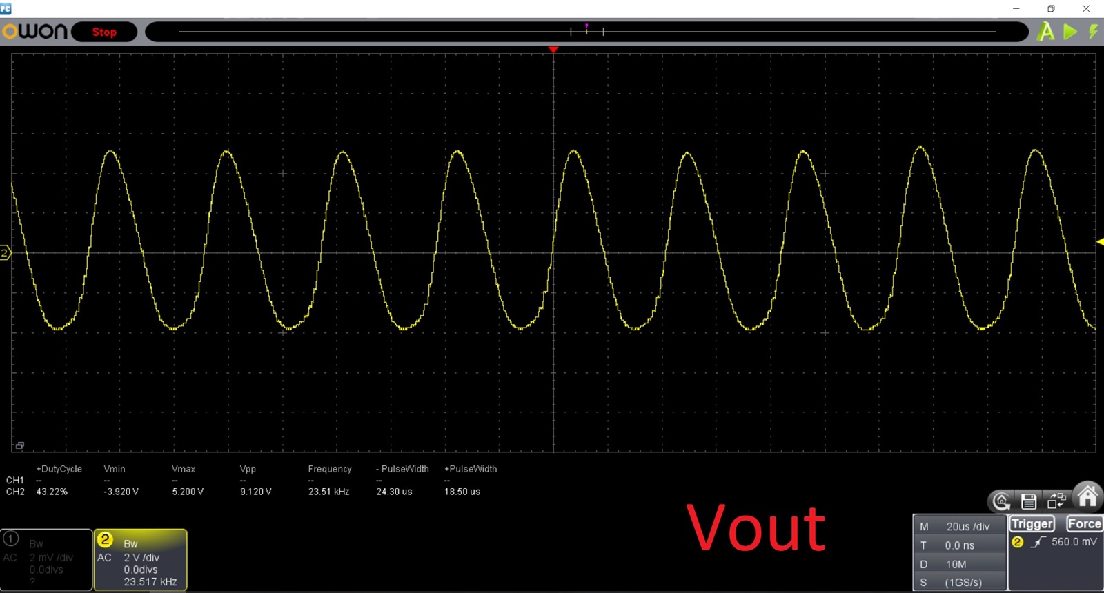
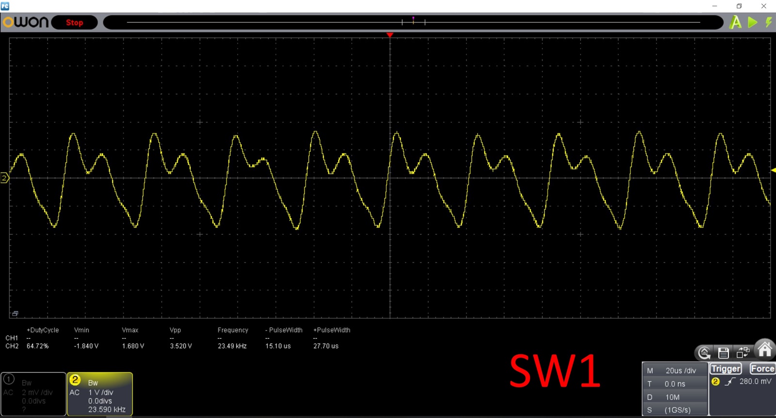
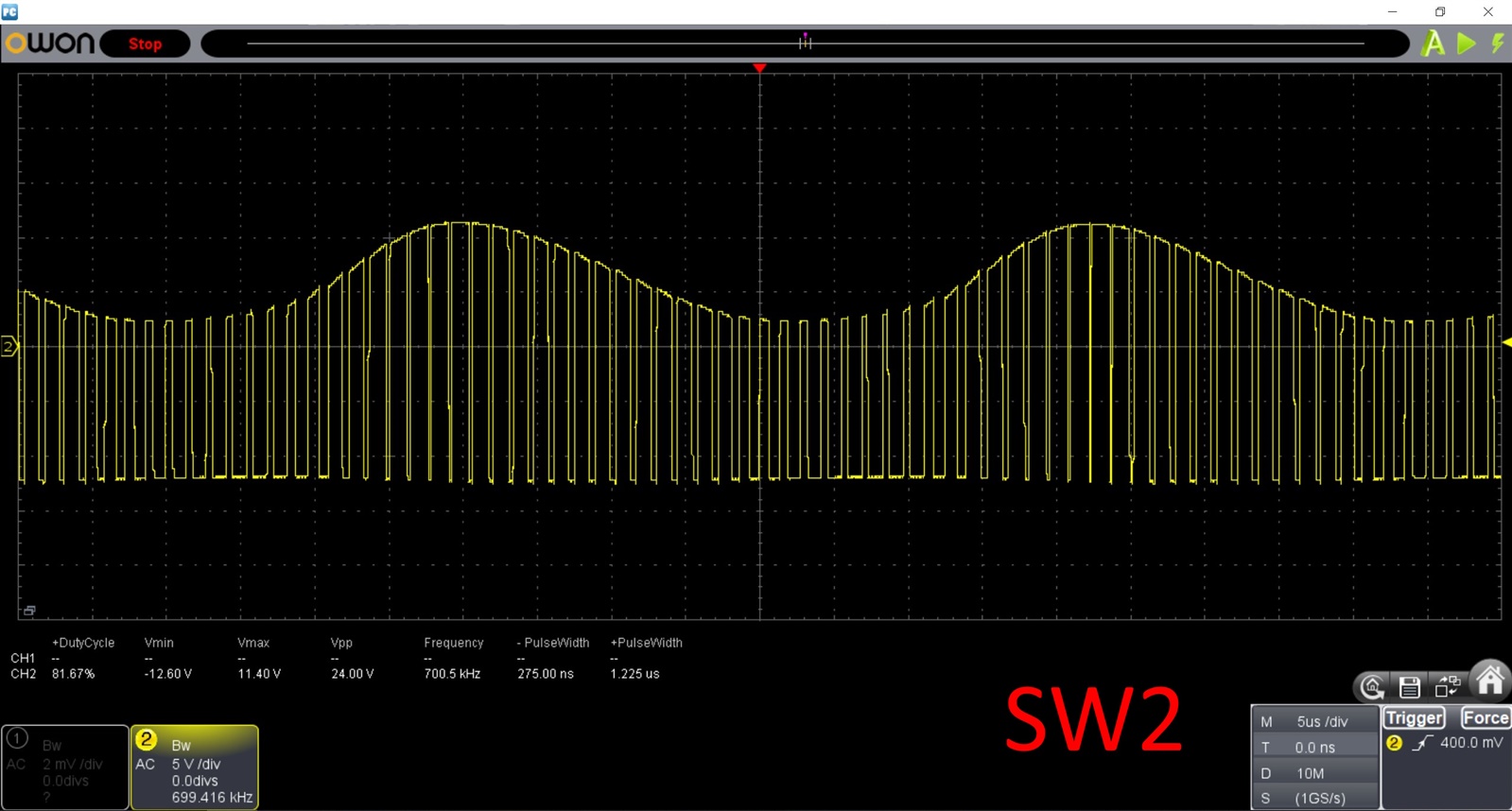
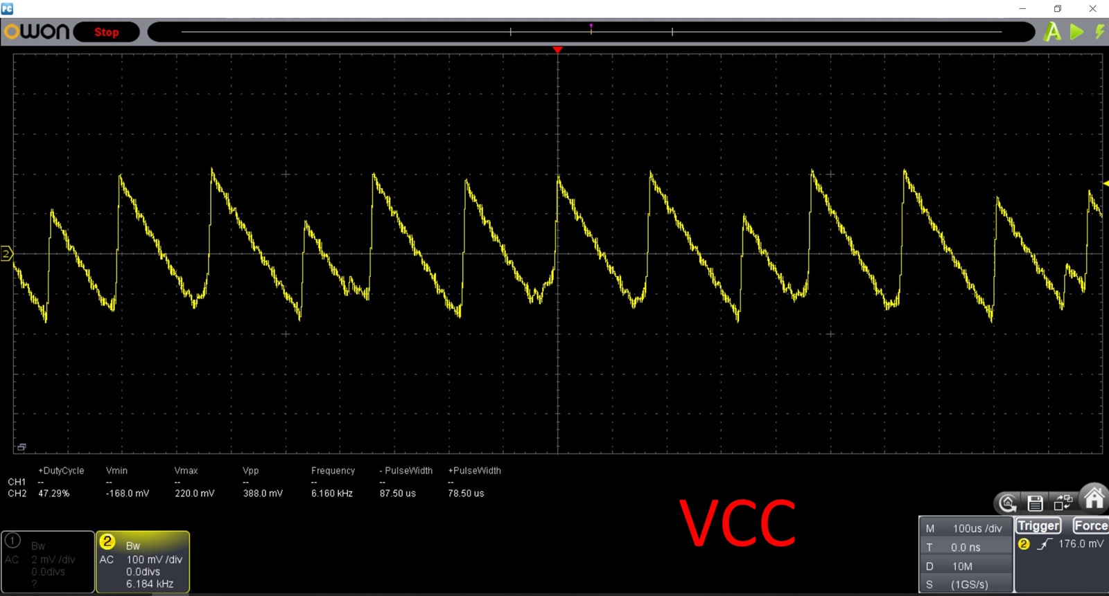
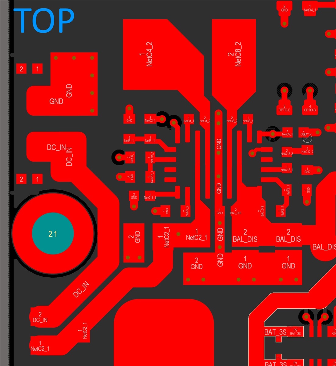
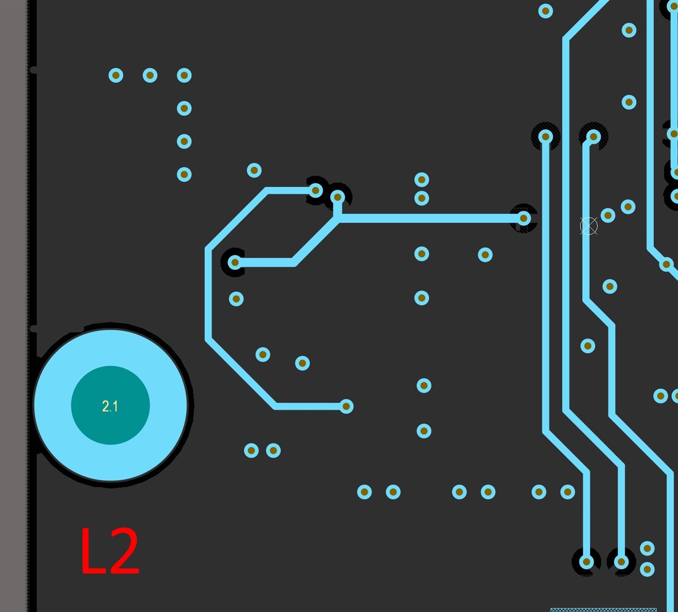
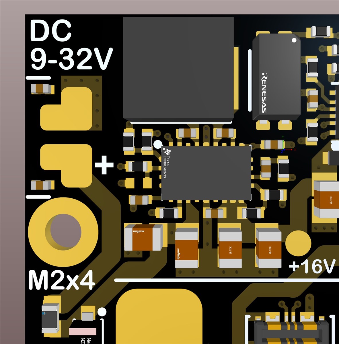
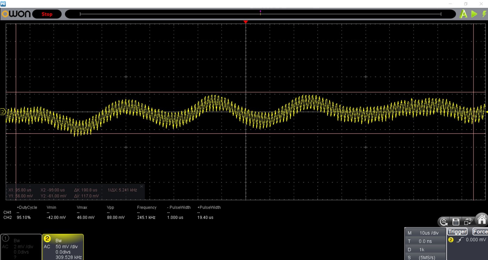
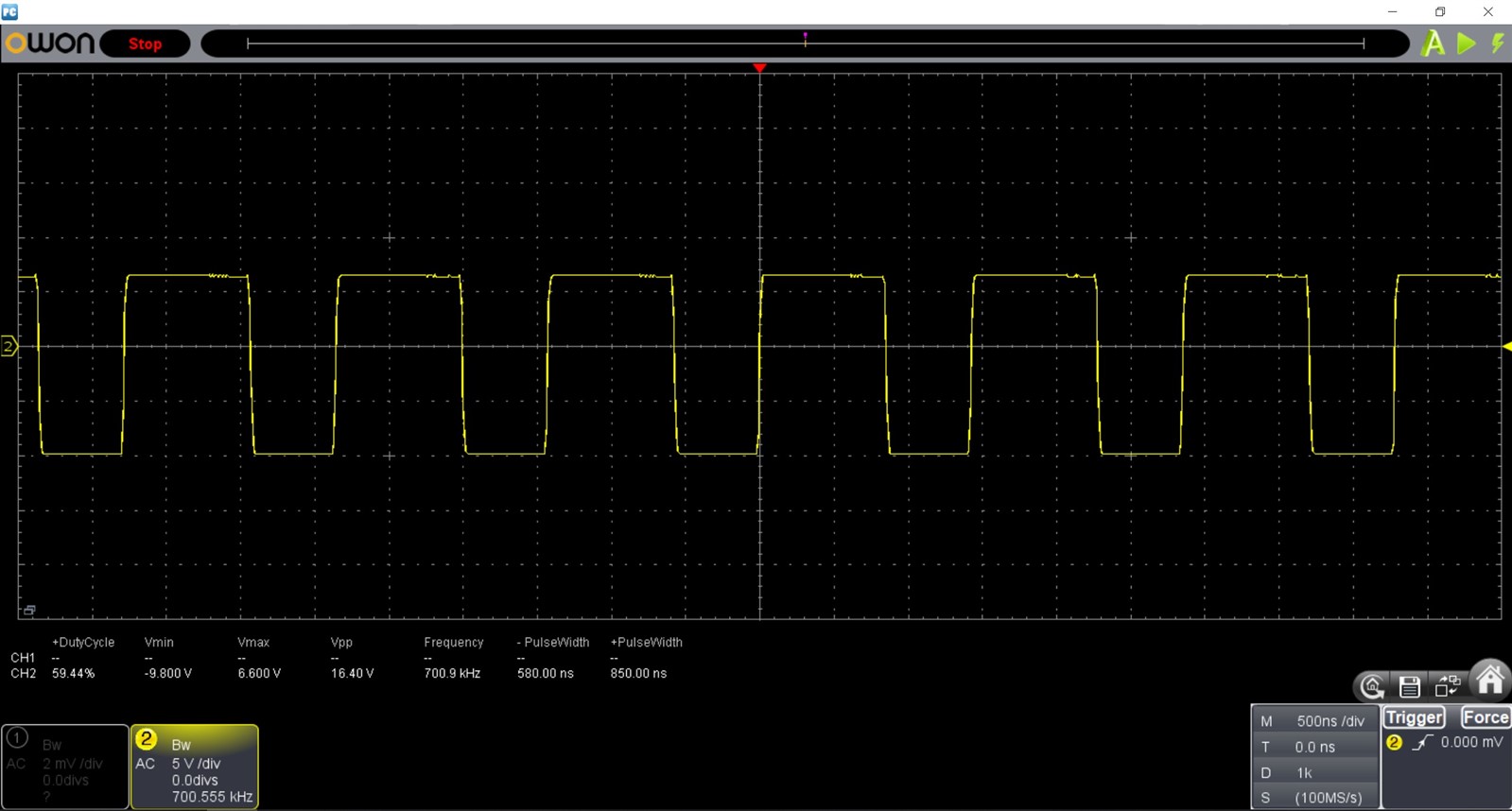
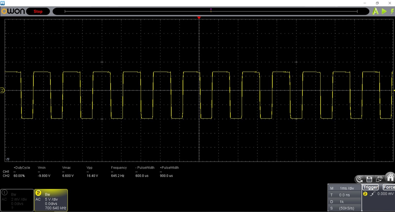
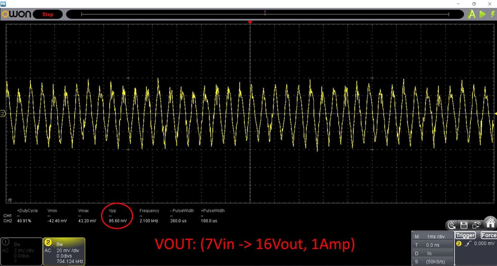
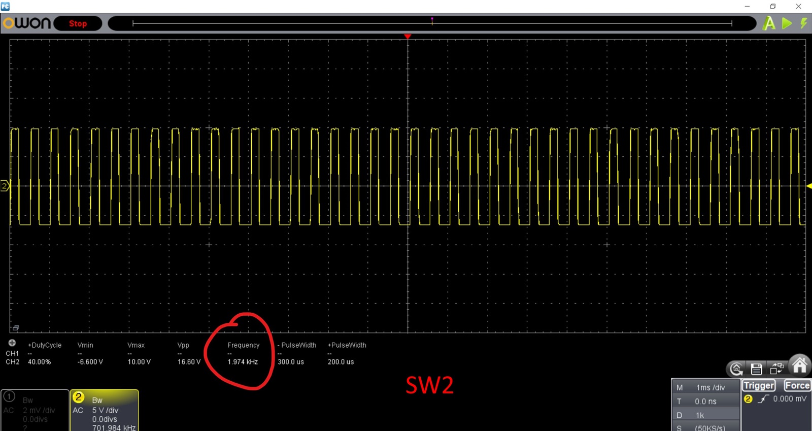
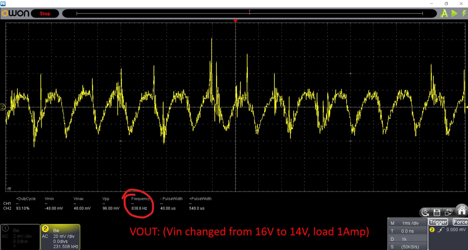
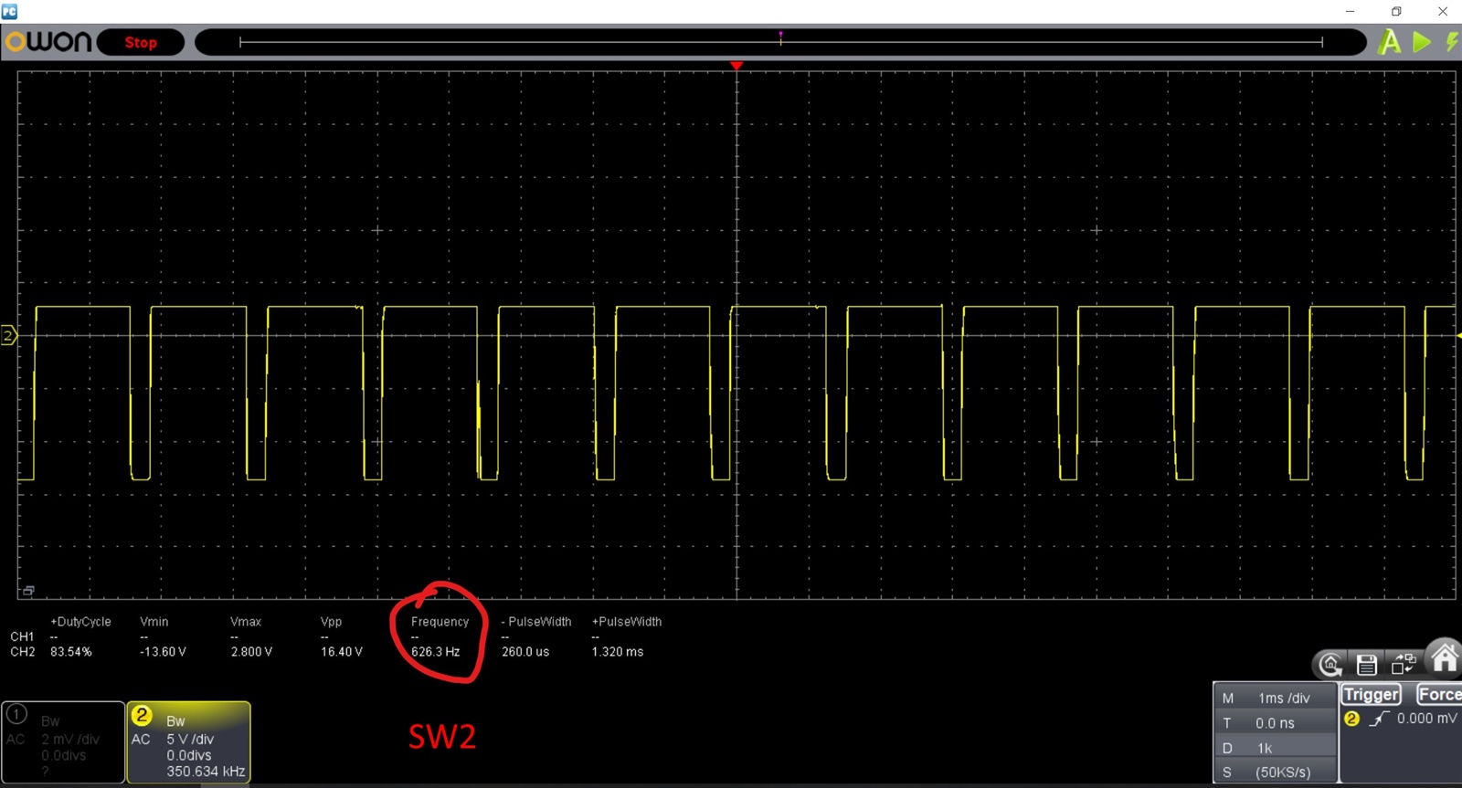
Hello. I am developing a compact charger for 3s lithium batteries using TPS552892-Q1 to get 16v from 9-32v input. It turned out that the prototype does not work properly. The input voltage is 12v. Without load, the output ripple is very high and the circuit is unstable. Do you have any idea what is wrong? Thanks.

  • Hi Ihor,

    This is because the compensation R6 C12 value is incorrect. Please follow below link https://www.ti.com/tool/download/TPS552892-CALCULATION-TOOL tool to calculate your R6 C12 to make phase margin>45° and gain margin>6dB.

    Recommend try R6=510Ohm and C12=22nF first.

  • Thank you. Indeed, the main issue was with the compensation network. Initially, I calculated a compensation network of 300 Ohms + 56nF using Webench. Later, I tested the values from the evaluation module. However, by mistake, the technician soldered a 300kOhm resistor instead of 300 Ohms, and unfortunately, I didn’t notice it right away.

    Now I have tested both 300 Ohms + 56nF and 510 Ohms + 22nF. The circuit has stabilized, and the efficiency seems good in both cases, but I would like to see lower output ripple. I also observe slight fluctuations in the output ripple. Do you have any ideas on how to fix this?

    In the updated version, I will add proper separation of analog and power grounds. However, during testing with wires, it hasn’t confirmed that the issue is related to grounding.

  • Hi Ihor,

    Please try connect DITH pin to GND to disable dithering. Thanks.

  • Yes, that was the first thing I tried, but it didn't work.

  • Hi,

    Do you know the output 22uF cap effective capacitance at 16V? The effective capacitance maybe low, leading to high voltage ripple, so you can try add more capacitors.Thanks.

  • The capacitors are rated for 35V, so I think the capacitance doesn’t decrease significantly. Interestingly, the PWM, which operates at 700kHz, has pauses at a frequency of 100–300Hz, and this changes depending on the chip temperature and input voltage. I feel like I’m missing something.

  • Hi Ihor,

    Actually from your PCB 3D view, I see output cap is 0805 size and from TDK, since you say it's 35V, so there's only one part C2012X5R1V226M125AC. Here you can see DC derating at 16V, the capacitance is only 2.325uF. This is not enough. You need add more caps.

  • Yes, indeed, it turned out that the capacitance drops significantly. I’ll need to take this into account in the future. I added a 100μF capacitor at the output — the ripple decreased, but it didn’t solve the instability issue. At the SW2 point and load 1A, I see a nice 700kHz PWM,

    but I also observe pauses in generation at a frequency of 100Hz–2kHz, which varies depending on the chip’s temperature.

    I tried adding another 4.7μF to VCC, connecting DITH and the FSW resistor to analog ground, and adding an RC filter to the MODE pin. The compensation network is 510Ω + 22nF. At the same time, the efficiency is within 92–96%, depending on the input voltage.

  • Hi Ihor,

    If you add a 100uF electrolytic cap, the compensation will need to change. Based on your now compensation value, I recommend you add some same TDK caps to see any improvement.

  • I installed five capacitors rated at 22μF 35V. The ripple has decreased, but a low-frequency ripple superimposed on the main frequency remains. I see that the controller does not change the PWM duty cycle depending on the load. That is, with or without load, the duty cycle remains around 60% at point SW2. It seems that the controller doesn't adjust the PWM duty cycle but rather operates in a relay-like mode, making PWM pauses instead of changing the duty cycle. Could this be the normal behavior of this chip? How is it supposed to work? The prototype currently looks like this:

  • Hi Ihor,

    Could you show the "low frequency ripple" waveform? There's always some noise in the circuit, so the switching frequency isn't exactly fixed. The jitter of on time/off time can cause this "low frequency ripple". Thanks.

  • The low PWM frequency ranges from a few hundred hertz to a couple of kilohertz and depends on the chip temperature, load, and other factors.

    If I raise the input voltage to 16V and lower it to 14V, I can get fairly large ripple.

  • Hi Ihor,

    The waveform is very normal. No issue. The ripple is normal. Thanks.

  • We are planning to launch a batch of 1000+ units for industrial use. Will this design work without issues? Thank you.

  • Hi Ihor,

    Could you double check MODE pin is connected to VCC or GND? Recommend to connect to VCC to configure in FPWM mode to get lowest ripple. And we need at least effective 30uF Cout, you need add more Cout caps.