This thread has been locked.

If you have a related question, please click the "Ask a related question" button in the top right corner. The newly created question will be automatically linked to this question.

UCC28740: Flyback Converter with UC24636

Part Number: UCC28740
Other Parts Discussed in Thread: UCC24636

Tool/software:

Hi, I am designing an AC/DC Converter with input: 57-270VAC and output is 5V,1A. I used the WEBENCH Power Designer tool and apply design with UCC28740 and UCC24636. 

This is the design suggested by WEBENCH:

/cfs-file/__key/communityserver-discussions-components-files/196/7510.WBDesign37.pdf

This is the design he implemented on my PCB:

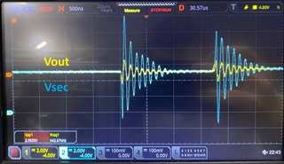
I use a 10ohm resistor as a load at the output and the output is as shown in the figure. What should I do to improve the output? There is a change of about 1V at the output. I have a different optocoupler component from WEBENCH. I used PC817 while WEBENCH used PS2811-1.

  • Please run the design calculator first to make sure the power stage design is correct. 

    https://www.ti.com/tool/download/SLUC487

    Please also capture the drive signal from the IC and overlay it with Vout. 

  • Hello Berkan,

    Can u confirm  power stage design of you board as below?

     can you confirm this is  your operating condition .?

    Your switching time is around 25us  @10 ohm load  right? 

    Can you get the gate drive signal and secondary winding voltage  along with vout  in same window?

    Make sure your output   capacitor is  mounted properly with no leads hanging on PCB. this may cause  lead inductance coming in to picture.

    Regards

    Dushyanth

  • Hi, thanks for replying.

    The WEBENCH says that the
    Fsw is 85.5kHz
    Ipmax =326mA
    Efficiency = 80.7%
    Transfomer:750811015

    My test Vin is 220VAC/50Hz. What else do you want to know, please notify me, thanks.

  • Hello Berkan,

    Thanks for the input. Power design should be ok. Increase the the R26 to 40 ohm ( secondary side snubber resistor)  for now, This is to damp the oscillations due to Ls leakage.  I will get back on this by  end of the day and  share me same  waveforms.

    Regards

    Dushyanth SR

  • Hello Dushyanth, thanks for replying. Here are new results with 40Ohm. It's look like secondary side voltage spike have increased. Note that the scale is 5V.( It was 2V on previous waveform).

  • Hello, Ning Tan. Thanks for replying. 
    Can The power stage designer be wrong that much ?
    I shared the drive signal at below. Please notify me.
    Thanks

  • Hi Berkan,

    Thanks for sharing waveform. 

    Here is the cause of ringing.

    Please reduce your inductance in the path of the load capacitance , it may be coming due to layout or or your capacitance ESL is more. You can try connecting more   capacitance with lower values in parallel for checking, so you effective ESL is less and also keep your  secondary  side  loop smaller in layout. for better performance. When primary switch turned off high di/dt  in to  output capacitance  with  high ESL is problem.

    Regards

    Dushyanth SR

  • Hi, Dushyanth,

    Are you sure about the problem. I tried to connect low ESL Output cap (WB1A477M0811MPF) but result is same as before

  • Hi Berkan,

    Problem is replicated in the  simulation.  This is  Vout  waveform with 10nH ESL. Please try jumping the  very straight wire  which can carry required load current form source of the secondary side FET  to Negative terminal of the capacitor directly.  This helps  to eliminate layout issue. Connect more capacitors of lesser value, which bring down the total ESL. Share me wave form with this experiments.

    Regards

    Dushyanth SR

  • Hi Berkan,

    Try putting ceramic caps in  parallel.   This may  reduce the stability but it helps in Vout ripple.  If you are not getting better  you can try putting

    https://www.digikey.com/en/product-highlight/p/panasonic/os-con-capacitors

    Oscon  SMD caps. Your ripple should go away,  Please perform wire jumping experiment to rule out the layout issue of PCB. 

    Regards

    Dushyanth SR

  • Hi Dushyanth,

    I added some ceramic capacitors like 10uF,1uF,100nF,10nF. I also did the wire jumper and the result is below:

    It reduced the ringing but as you can see it is still too much. Do you think I should continue adding capacitors? It doesn't seem like a proper solution. It seems like there is another problem that I need to fix. But I don't know what it is. Do you have any suggestions?

  • Hi  Berkan,

    Thank you for getting the improved waveform.   Can you say me with the  increase in the load , how the  ripple amplitude varies? give me four waveforms

    of 25%, 50%, 75%, full load, with the ceramic caps.