Tool/software:
from smbus2 import SMBus
import time
import RPi.GPIO as GPIO

BQ25703A_I2C_ADDRESS        = 0x6b
BQ25703A_MANUFACTURER_ID    = 0x40
BQ25703A_DEVICE_ID          = 0x78

MANUFACTURER_ID_ADDR        = 0x2E
DEVICE_ID_ADDR              = 0x2F
MAX_CHARGE_VOLTAGE_ADDR     = 0x04
CHARGE_CURRENT_ADDR         = 0x02
CHARGE_OPTION_0_ADDR        = 0x00
MINIMUM_SYSTEM_VOLTAGE_ADDR = 0x0D
CHARGE_STATUS_ADDR          = 0x20
ADC_OPTION_ADDR             = 0x3A
VBUS_ADC_ADDR               = 0x27
PSYS_ADC_ADDR               = 0x26
VSYS_ADC_ADDR               = 0x2D
VBAT_ADC_ADDR               = 0x2C
ICHG_ADC_ADDR               = 0x29
IDCHG_ADC_ADDR              = 0x28
IIN_ADC_ADDR                = 0x2B

EN_LWPWR                    = 0b0
EN_OOA                      = 0b1

CHARGING_ENABLED_MASK       = 0b00000100
ADC_ENABLED_BITMASK         = 0b01010111
ADC_START_CONVERSION_MASK   = 0b01100000
ADC_CONT_CONVERSION_MASK    = 0b10100000

#Max voltage register 1 values
MAX_VOLT_ADD_16384_MV       = 0b01000000
MAX_VOLT_ADD_8192_MV        = 0b00100000
MAX_VOLT_ADD_4096_MV        = 0b00010000
MAX_VOLT_ADD_2048_MV        = 0b00001000
MAX_VOLT_ADD_1024_MV        = 0b00000100
MAX_VOLT_ADD_512_MV         = 0b00000010
MAX_VOLT_ADD_256_MV         = 0b00000001

#Max voltage register 2 values
MAX_VOLT_ADD_128_MV         = 0b10000000
MAX_VOLT_ADD_64_MV          = 0b01000000
MAX_VOLT_ADD_32_MV          = 0b00100000
MAX_VOLT_ADD_16_MV          = 0b00010000

#Minimum system voltage register values
MIN_VOLT_ADD_8192_MV        = 0b00100000
MIN_VOLT_ADD_4096_MV        = 0b00010000
MIN_VOLT_ADD_2048_MV        = 0b00001000
MIN_VOLT_ADD_1024_MV        = 0b00000100
MIN_VOLT_ADD_512_MV         = 0b00000010
MIN_VOLT_ADD_256_MV         = 0b00000001

VBUS_ADC_SCALE              = 0.064
VBUS_ADC_OFFSET             = 3.2

PSYS_ADC_SCALE              = 0.012

VSYS_ADC_SCALE              = 0.064
VSYS_ADC_OFFSET             = 2.88

VBAT_ADC_SCALE              = 0.064
VBAT_ADC_OFFSET             = 2.88

ICHG_ADC_SCALE              = 0.064

IIN_ADC_SCALE               = 0.050

MAX_CHARGE_CURRENT          = 8.128
MIN_CHARGE_CURRENT          = 0.064
MAX_CURR_LSB_VAL_MA         = 64
MAX_CHARGING_POWER          = 60000
MAX_CURR_REG_SHIFT          = 6
MAX_CURR_REG_03_MASK        = 0b00011111
MAX_CURR_REG_02_MASK        = 0b11000000

MAX_VSYS_VOLTAGE            = 19.2
MAX_VOLT_LSB_VAL_MV         = 16
MAX_VOLT_REG_SHIFT          = 4
MAX_VOLT_REG_05_MASK        = 0b01111111
MAX_VOLT_REG_04_MASK        = 0b11110000
VSYS_MIN_MV                 = 1024
VSYS_MIN_LSB_MV             = 256

class bq25703a:
    i2c_address = BQ25703A_I2C_ADDRESS
    i2c_bus = 1
    ilim_hiz_pin = 21

    connected = 0
    charging_status = 0
    vbat_voltage = 0
    vbus_voltage = 0
    vsys_voltage = 0
    input_current = 0
    charge_current = 0
    max_charge_current_ma = 0

    def __init__(self, bus = i2c_bus, address = i2c_address, ilim_hiz_pin = ilim_hiz_pin):
        self.i2c_bus = bus
        self.i2c_address = address
        self.ilim_hiz_pin = ilim_hiz_pin
        print("Starting bq25703a Interface on I2C bus " + str(self.i2c_bus) + " with address " + str(hex(self.i2c_address)))

        GPIO.setmode(GPIO.BCM)
        GPIO.setup(self.ilim_hiz_pin, GPIO.OUT)
        GPIO.output(self.ilim_hiz_pin, 0)

        try:
            with SMBus(self.i2c_bus) as smbus:
                # Get the manufacturer id
                manufacturer_id = smbus.read_byte_data(self.i2c_address, MANUFACTURER_ID_ADDR)
                # Get the device id
                device_id = smbus.read_byte_data(self.i2c_address, DEVICE_ID_ADDR)
                # Set the ADC Options
                smbus.write_byte_data(self.i2c_address, ADC_OPTION_ADDR, ADC_ENABLED_BITMASK)

                charge_option_0_register_1_value = 0b00100110
                smbus.write_byte_data(self.i2c_address, CHARGE_OPTION_0_ADDR + 1, charge_option_0_register_1_value)
                charge_option_0_register_2_value = 0b00001110
                smbus.write_byte_data(self.i2c_address, CHARGE_OPTION_0_ADDR, charge_option_0_register_2_value)
        except:
            manufacturer_id = 0
            device_id = 0

        if ((device_id == BQ25703A_DEVICE_ID) and (manufacturer_id == BQ25703A_MANUFACTURER_ID)):
            self.connected = 1
            print("bq25703a connected")
        else:
            self.connected = 0
            print("bq25703a not found!")

    # @brief Returns whether the regulator is charging
    # @retval uint8_t 1 if charging, 0 if not charging
    def Get_Regulator_Charging_State(self):
        with SMBus(self.i2c_bus) as smbus:
            data = smbus.read_byte_data(self.i2c_address, CHARGE_STATUS_ADDR)

        if (data and CHARGING_ENABLED_MASK):
            self.charging_status = 1
        else:
            self.charging_status = 0

        return self.charging_status

    def Set_Charge_Voltage(self, voltage):
        round(voltage, 3)
        if (voltage > MAX_VSYS_VOLTAGE):
            voltage = MAX_VSYS_VOLTAGE
        if (voltage < (VSYS_MIN_MV/1000)):
            voltage = (VSYS_MIN_MV/1000)
        #convert to mV
        voltage = int(voltage * 1000)
        #Make sure the value is divisiable by 16mV
        while ((int(voltage) % MAX_VOLT_LSB_VAL_MV) != 0):
            #increment down until voltage is divisiable by 16mV
            voltage = voltage - 1

        minimum_system_voltage_value = voltage - 5000
        while ((minimum_system_voltage_value % VSYS_MIN_LSB_MV) != 0):
            #increment down until minimum_system_voltage_value is divisiable by VSYS_MIN_LSB_MV
            minimum_system_voltage_value = minimum_system_voltage_value - 1
        if (minimum_system_voltage_value < VSYS_MIN_MV):
            minimum_system_voltage_value = VSYS_MIN_MV

        minimum_system_voltage_value = minimum_system_voltage_value / VSYS_MIN_LSB_MV

        voltage = voltage / MAX_VOLT_LSB_VAL_MV

        voltage_list = [((int(voltage) << 4) & MAX_VOLT_REG_04_MASK), ((int(voltage) >> 4) & MAX_VOLT_REG_05_MASK)]

        with SMBus(self.i2c_bus) as smbus:
            smbus.write_byte_data(self.i2c_address, MINIMUM_SYSTEM_VOLTAGE_ADDR, int(minimum_system_voltage_value))
            smbus.write_i2c_block_data(self.i2c_address, MAX_CHARGE_VOLTAGE_ADDR, voltage_list)

    def Set_Charge_Current(self, current):
        current = float(current)
        round(current, 3)
        if (current > MAX_CHARGE_CURRENT):
            current = MAX_CHARGE_CURRENT
        if (current < MIN_CHARGE_CURRENT):
            current = MIN_CHARGE_CURRENT

        #convert to mA
        current = int(current * 1000)
        self.max_charge_current_ma = current
        #Make sure the value is divisiable 64mA
        while ((int(current) % MAX_CURR_LSB_VAL_MA) != 0):
            #increment down until current is divisiable by 64mA
            current = current - 1

        current = current / MAX_CURR_LSB_VAL_MA

        current_list = [((int(current) << 6) & MAX_CURR_REG_02_MASK), ((int(current) >> 2) & MAX_CURR_REG_03_MASK)]

        with SMBus(self.i2c_bus) as smbus:
            smbus.write_i2c_block_data(self.i2c_address, CHARGE_CURRENT_ADDR, current_list)

        GPIO.output(self.ilim_hiz_pin, 1)

    def Read_Charger_Status(self):
        with SMBus(self.i2c_bus) as smbus:
            data = smbus.read_byte_data(self.i2c_address, CHARGE_STATUS_ADDR + 1)
            print("Charge Status Address 0x21 = " + str(bin(data)))
            data = smbus.read_byte_data(self.i2c_address, CHARGE_STATUS_ADDR)
            print("Charge Status Address 0x20 = " + str(bin(data)))

    # @brief Gets VBAT voltage that was read in from the ADC on the regulator
    # @retval VBAT voltage in volts
    def Get_VBAT_ADC_Reading(self):
        self.__read_adc()
        return self.vbat_voltage

    # @brief Gets VBUS voltage that was read in from the ADC on the regulator
    # @retval VBUS voltage in volts
    def Get_VBUS_ADC_Reading(self):
        self.__read_adc()
        return self.vbus_voltage

    # @brief Gets Input Current that was read in from the ADC on the regulator
    # @retval Input Current in amps
    def Get_Input_Current_ADC_Reading(self):
        self.__read_adc()
        return self.input_current

    # @brief Gets Charge Current that was read in from the ADC on the regulator
    # @retval Charge Current in amps
    def Get_Charge_Current_ADC_Reading(self):
        self.__read_adc()
        return self.charge_current

    # @brief Gets the max output current for charging
    # @retval Max Charge Current in miliamps
    def Get_Max_Charge_Current(self):
        self.__read_adc()
        return self.max_charge_current_ma

    def __read_adc(self):
        with SMBus(self.i2c_bus) as smbus:
            # Perform single conversion
            smbus.write_byte_data(self.i2c_address, (ADC_OPTION_ADDR+1), ADC_START_CONVERSION_MASK)

            conversion_finished = 0
            while (conversion_finished == 0):
                data = smbus.read_byte_data(self.i2c_address, (ADC_OPTION_ADDR+1))
                conversion_finished = (data and (1<<6))
                time.sleep(0.05)

            data = smbus.read_byte_data(self.i2c_address, VBAT_ADC_ADDR)
            self.vbat_voltage = (data * VBAT_ADC_SCALE) + VBAT_ADC_OFFSET

            data = smbus.read_byte_data(self.i2c_address, VSYS_ADC_ADDR)
            self.vsys_voltage = (data * VSYS_ADC_SCALE) + VSYS_ADC_OFFSET

            data = smbus.read_byte_data(self.i2c_address, ICHG_ADC_ADDR)
            self.charge_current = data * ICHG_ADC_SCALE

            data = smbus.read_byte_data(self.i2c_address, IIN_ADC_ADDR)
            self.input_current = data * IIN_ADC_SCALE

            data = smbus.read_byte_data(self.i2c_address, VBUS_ADC_ADDR)
            self.vbus_voltage = (data * VBUS_ADC_SCALE) + VBUS_ADC_OFFSET

    def check_hidrv1_activation(self):
        with SMBus(self.i2c_bus) as smbus:
            # Lese Charge Status Register (Adresse kann je nach Chip variieren)
            status = smbus.read_byte_data(self.i2c_address, CHARGE_STATUS_ADDR)
            print(f"Charge Status Register: {bin(status)}")

            # Überprüfe, ob das System im Hi-Z-Modus ist
            adc_option = smbus.read_byte_data(self.i2c_address, ADC_OPTION_ADDR)
            print(f"ADC Option Register: {bin(adc_option)}")

    def read_register_20h(self):
        with SMBus(self.i2c_bus) as smbus:
            register_address = 0x20
            wert = smbus.read_byte_data(self.i2c_address, register_address)
            print(f"Register 0x20: {hex(wert)}")
            return wert


if __name__ == "__main__":
    # Instanz erstellen
    device = bq25703a()

    # Überprüfen, ob das Gerät verbunden ist
    if device.connected:
        print("Gerät ist verbunden.")

        while True:

            # Ladezustand abfragen
            charging_state = device.Get_Regulator_Charging_State()
            print(f"Ladevorgang läuft: {'Ja' if charging_state else 'Nein'}")

            # Batterienspannung und Versorgungsspannungen auslesen
            vbat = device.Get_VBAT_ADC_Reading()
            vbus = device.Get_VBUS_ADC_Reading()

            print(f"VBAT: {vbat:.3f} V")
            print(f"VBUS: {vbus:.3f} V")


            # Eingabestrom auslesen
            input_current = device.Get_Input_Current_ADC_Reading()
            print(f"Eingangsstrom: {input_current:.3f} A")

            # Ladestrom und Max. Ladestrom auslesen
            charge_current = device.Get_Charge_Current_ADC_Reading()
            max_charge_current = device.Get_Max_Charge_Current()
            print(f"Ladestrom: {charge_current:.3f} A")
            print(f"Max. Ladestrom: {max_charge_current:.1f} mA")

            # Beispiel: Ladespannung auf 4,2 V setzen
            device.Set_Charge_Voltage(4.2)
            print("Ladespannung auf 4,2 V gesetzt.")

            # Beispiel: Ladestrom auf 2 A setzen
            device.Set_Charge_Current(2)
            print("Ladestrom auf 2 A gesetzt.")

            # Optional: Lade-Status auslesen
            device.Read_Charger_Status()

            device.check_hidrv1_activation()

            device.read_register_20h()
            print("----------------------------------------------------------------")
            time.sleep(3)
    else:
        print("Gerät nicht verbunden.")
Dear Texas Instruments Support Team,
I am a student from Switzerland and for my thesis I am currently working with a BQ25703A
I am trying to operate my system without a battery connected, primarily for testing purposes.
Problem:
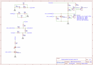
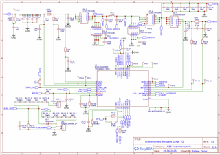
I am seeing a voltage drop across MOSFET Q2-1, which is driven by HIDRV1. I have 5.2V before the MOSFET, but only 1.3V after it. This indicates that the MOSFET is blocking the voltage.
A schematic of my setup is attached for your reference.
Question:
What configuration settings are necessary to allow the voltage to pass through Q2-1 and reach VSYS, enabling system operation without a battery? Which registers and bits control this?
Goal: I want to power the system connected to VSYS from the input source even with no battery.
The CELL_BATPRESZ pin is currently Permanently tied LOW.
Future Intention:
I also plan to use the BQ25703A with a 4-cell battery pack in the future. Is the attached code snippet suitable for a 4-cell configuration, or will register values need to be changed?
I have attached a snippet of my current initialization code below:
I would appreciate any guidance you can provide to resolve this voltage blocking issue and ensure proper system operation without a battery.
Thank you for your time and expertise.
Sincerely,
Fabian