This thread has been locked.

If you have a related question, please click the "Ask a related question" button in the top right corner. The newly created question will be automatically linked to this question.

BQ25798: Short-circuit protection while operating from charger power

Part Number: BQ25798
Other Parts Discussed in Thread: TPS25750, BQ40Z50, TPS63802, TPS2560A, BQ25672

Tool/software:

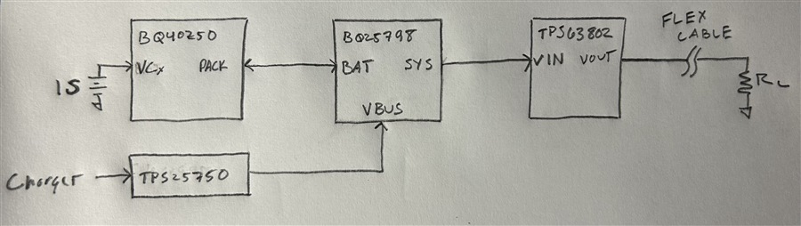
Hi there—our 1S design comprises TPS25750 + BQ25798 + BQ40Z50. The SYS output of the BQ25798 drives a 3.3-V buck/boost similar to TPS63802 (2-A continuous, 4-A peak switch current), which then drives a load by way of a flex cable. A simplified diagram of our power path is shown below:

We wish to implement short-circuit protection to prevent excessive temperature rise across the flex cable in case the downstream load fails short. The flex cable cannot withstand currents near the peak current limit of the TPS63802, and the maximum sustained short-circuit current must be limited to approximately 2 A.

At present, we use the over-current in discharge (OCD) function of the BQ40Z50 to protect everything downstream of SYS. This function is very convenient because it does not add to our standby power budget, and the delay is programmable.

However, this function can only protect everything downstream of SYS while the system operates from battery power. While the system operates from charger power, the BQ40Z50 is effectively bypassed and the peak switch current of the TPS63802 becomes the limiting factor.

We have considered adding a current-limited load switch such as TPS2560A after SYS, but the reaction time of these devices is too short (~3.5 us). The load downstream of the flex cable can demand 3–4 A of inrush for 1–2 ms, and there is too much risk that a fast-reacting load switch may interrupt prematurely. Our only other idea is a fuse, but its behavior is not well controlled.

We are seeking ideas on how to implement HW-redundant short-circuit protection that can cover both the battery-powered and charger-powered cases. Can TI recommend any other solutions that we may not have considered? Thank you in advance—in case I can provide any additional information about our application, please let me know.

  • Hi Jeff,

    You can limit the charger's input current and therefore total ISYS + ICHG but that extends charge time due to lower ICHG.  Also, the input current limit feedback loop response time is in the ~10 millisecond range.  Or you could replace TPS63802 with another BQ25798 (or the lower current BQ25672) running in OTG/reverse mode (requires I2C to turn on). In OTG, the converter can regulate output voltage or output current.  If regulating output current to 2A, output voltage drops.  Since both the BQ25798 and BQ25672 have the same I2C address, an I2C multi-plexer might be required.  

    Regards,

    Jeff

  • Hi Jeff—thank you for your prompt support! We did consider throttling the input current, which so far seems to be the least of all evils.

    One idea was to continuously monitor the input power reported by the BQ25798, and lower the input current if the input power is suspiciously high compared to the input power reported by the BQ40Z50. But this is a FW solution, which can fail or be circumvented; we're hoping to identify a pure HW solution.

    Changing the buck/boost to another BQ25xxx is an interesting idea, but likely cost-prohibitive. Not shown in my block diagram is also a second TPS63802-like device that supplies 3.7 V to another group of loads that must also be protected—this second buck/boost supplies our PMIC which then supplies our MCU, so there would be nothing available to enable another BQ25xxx over I2C.

    Are there any other methods or TI devices that could help here? If we can at least detect a fault somehow, we can drive an NMOS connected to the /QON pin of the BQ25798 to reset it; this would force the input current limit back to the safe value set by the ILIM_HIZ pin. Perhaps TI offers some kind of supervisor IC with an interrupt output that we can debounce or delay?

    Thanks again for your continued support—I realize this is really a system-level design question and not so much BQ25798-specific; I really appreciate it.

  • Hi Jeff,

    TI has a whole suite of voltage supervisor circuits but I don't see how they will help monitor current/power.  You could use an INAxxx current sense amplifier with series sense resistor but those don't have debounce or delay, only analog output that is proportional to the sense current.  I'm surprised there is not a current limit switch with a delay.  Good luck! 

    Regards,

    Jeff

  • Hi Jeff—thank you for your feedback!

    A current sense amplifier is a viable approach, but it's a bit of a science project for what we're looking to do. We have since found some current-limiting load switches from another vendor that seem to fit the bill here, so we're going to head down that path for now.

    Thanks again for your continued support—enjoy the long weekend!