This thread has been locked.

If you have a related question, please click the "Ask a related question" button in the top right corner. The newly created question will be automatically linked to this question.

BQ25792: LOST SYS OUTPUT. CHIP SEEMS TO HAVE FAILED

Part Number: BQ25792
Other Parts Discussed in Thread: BQ25798, , EV2400

Tool/software:

I am developing a new instrument which includes the BQ25792 to manage the battery charging and USB power.

We have been working with the first prototype PCB's and had 3 with apparently failed BQ25792's.

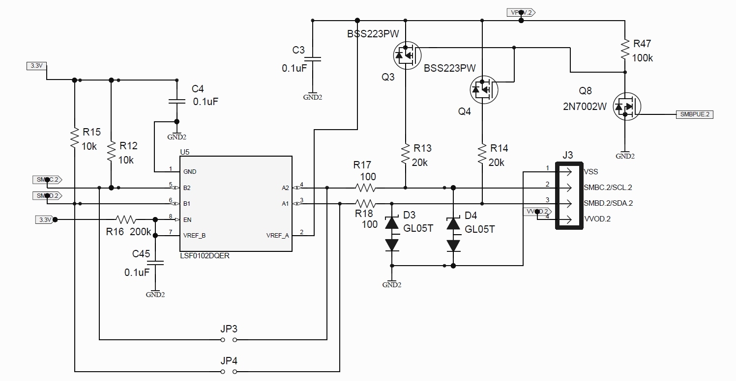
This is the charger part of the schematic:-

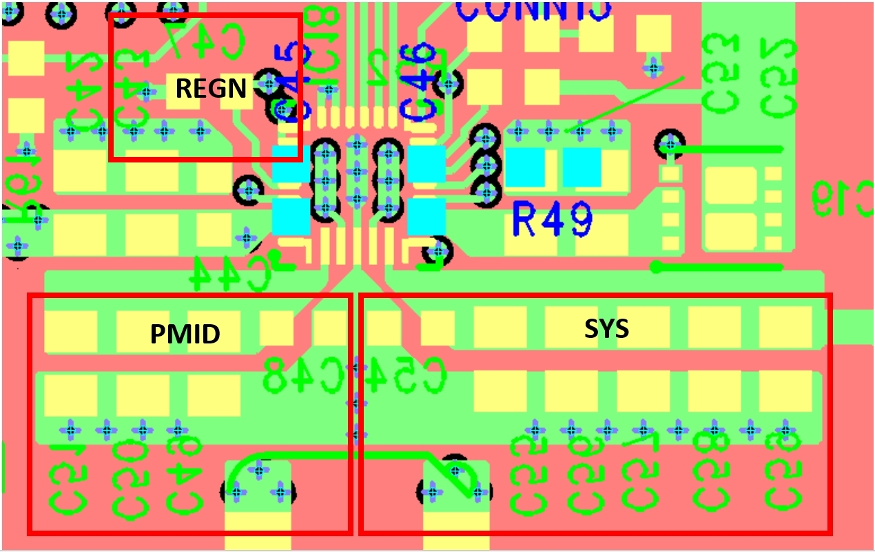
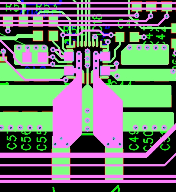
This is the charger layout:-

The VBUS comes from a 5V 2.5A USB charger. The battery is a 21700 2S1P 7.2V 4.9Ah.

We rely on the SYS output to power the rest of the circuit.

A button connected to SYS at BUTTON_ON turns Q5 on, then a PIC holds it on at POWER_ON until the system is turned off.

When we get this failure, the SYS output just stays at close to 0V with VBUS connected, the battery connected, or both.

We suspect it may be related to a register setting we are applying, but cannot pin it down to a particular one.

It may also only happen when a battery is connected. Running just on VBUS hasn't caused the failure as yet.

Registers we were setting are:-

CHARGER_CONTROL_1,0 - DISABLE WATCHDOG TIMER

CHARGER_CONTROL_0,176 - ENABLE ICO

CHARGER_CONTROL_5,183 - ENABLE SHIP FET; ENABLE IBAT DISCHARGE CURRENT SENSING FOR ADC; ENABLE BATTERY DISCHARGING CURRENT OCP

PRECHARGE_CONTROL, 198 - 240mA

MINIMAL_SYSTEM_VOLTAGE, 18 - 7V

CHARGE_VOLTAGE_LIMIT, 840 - 8.4V

CHARGE_CURRENT_LIMIT, 50 - 500mA

INPUT_CURRENT_LIMIT, 300 - 3A

ADC_CONTROL, 0x8c - ENABLE ADC; 15BIT; START AV USING NEW ADC CONVERSION

I have since read that BQ25798 may be a better option for us, as in some applications a battery won't be fitted.

BQ25798 is more suitable if a battery might not be fitted in some applications? Is that correct?

Are there any differences between BQ25792 and BQ25798 we need to consider if we change?

It appears to be a PIN2PIN equivalent physically, but are there any register differences or other circuit differences we will need to consider?

Thanks in advance for any help you can provide.

Best Regards,

Julian Kent

  • Hi Julian,

    I don't see any issues with the registers. BQ25798 and BQ25792 are pin 2 pin and reg 2 reg compatible.  If charge can be disabled with either CE pin or bit when there is no battery or open pack protector due to discharged battery, then BQ25792 is okay. Otherwise BQ25798 is best because it does not turn off the converter for 30ms after BAT OVP, causing SYS collapse, like BQ25792.

    On these failures, does the IC restart after power cycle or are the ICs damaged? 

    Regards,

    Jeff

  • Hi Jeff,

    Thanks for the quick response!

    That's useful to know we can switch to the BQ25798 easily. We have now implemented disabling charge bit if no battery detected, but were a bit worried that there will be a period of time after plugging in external power until the PIC powers up, detects no battery, then disables charging. Within that time period the SYS could drop due to a BAT OVP. If CE is still low and we disable the charge bit, does that still disable charging?

    The failures appear to be permanently damaged. Reapplying the VBUS or Battery results in no SYS output.

    We have also tried powering the PIC separately to try and communicate with the failed charger via I2C, but aren't getting any comms either.

    Regards,

    Julian

  • Hi Julian,

    Both /CE pin = low and CE pin=1 is required for charging.  

    I am surprised by the damaged IC with such low power application.  Your layout looks ok.  Most important caps are the REGN, PMID and SYS caps.  Their voltage rating should be at least 2x their applied voltage to account for derating. Their ground returns to IC GND pin need to be short, low inductive traces/pours.   

    Regards,

    Jeff

  • Hi Jeff,

    I have reviewed the capacitors I am using. All PMID and SYS capacitors are 25V X7R. The REGN is a 16V X7R. I have checked the BQ25792EVM BoM and that uses a 16V X5R on REGN and 25V on the others except the 100nF's which are 50V. I was intending to change them all to exactly the same as the EVM on the next iteration of my board.

    In terms of the ground returns the PMID and SYS capacitors connect to a copper pour on the same side as the charger. The REGN capacitor ground however is connected to a ground plane layer. See below:-

    What do you think?

    Regards,

    Julian

  • Hello Julian,

    Thanks for being patient with this. I'll get back to you next week on this question.

    Best Regards,
    Ethan Galloway

  • Hello Julian,

    Once again, thanks for being patient with this.

    This layout looks good. Also, it might be good to make the top GND plane larger to also include the REGN capacitor.

    Just for reference, we generally recommend closely following the example layout in the datasheet for the BQ25798.

    Best Regards,
    Ethan Galloway

  • Hi Ethan,

    Thank you for your response. I will look at extending the top GND to include the REGN capacitor.
    But I assume you don't think this could be the root cause of the chip failures we have been seeing?

    I was originally thinking it might have been a register setting we were applying, but Jeff F couldn't see any issues with our Register settings.

    The only other thing I can think of which may be causing it, is we have since found out that the batteries we are using (which are prototypes at the moment) have an issue with the internal battery management electronics, which may allow the 2S 21700 cells to go out of balance. Do you think, if this was the case, that could cause catastrophic damage to the BQ25792 chip?

    Regards,

    Julian

  • Hello Julian,

    But I assume you don't think this could be the root cause of the chip failures we have been seeing?

    No, I don't think this is related to the root cause of the failures you've been seeing.

    Do you think, if this was the case, that could cause catastrophic damage to the BQ25792 chip?

    I think the cells going out of balance could cause catastrophic damage to the BQ25792 chip, but I don't think this is likely. Do you know what the cells were doing when the BQ25792 was damaged?

    Best Regards,
    Ethan Galloway

  • Hi Ethan,

    No unfortunately I don't know exactly what state the cells were in when the failures happened.

    As an aside I have been speaking to the company developing our new battery pack and they have said they have seen this quite regularly on TI chargers. They have said that if a pack gets into a shutdown state (the PCM has disconnected the cells from the outside world due to overvoltage or short circuit detection) then it is connected to the charger and an external power supply is connected, the charger can put full battery voltage on the comms lines, damaging the charger IC and potentially the micro-controller it is connected to.

    They think this is because when the battery is close to 0V, when the external power supply is connected the battery ground is 'floating' so the potential on the comms lines can become elevated to battery voltage.

    They have recommended putting protection on the comms lines, something like this extract from your EV2400 circuit:-

    I was going to put the TVS diodes on all lines I am taking to our micro-controller as a precaution.

    What do you think about this?

    Have you heard about this problem?

    Regards,

    Julian

  • Hi Julian,

    I haven't heard of this problem but protection on the comm lines definitely will not hurt.  With no battery or open protector, the BQ25798 clamps the BAT voltage to ~2.4V*# of cells for about 1.5 seconds while applying the trickle charge current = 100mA to close the pack protector.  But after 1.5s, the charger starts a full charge cycle. If the pack protector has not closed by then, the pack input sees the full battery voltage.  Maybe there is capacitive coupling to the lines?  

    Regards,

    Jeff