This thread has been locked.

If you have a related question, please click the "Ask a related question" button in the top right corner. The newly created question will be automatically linked to this question.

TPS23861: TPS23861 TPS23753APWR 1port input 4 port output poe ethernet switch schematic check

Part Number: TPS23861
Other Parts Discussed in Thread: TPS23753A, TPS2373, TPS2372, TPS2378, TPS23731

Tool/software:

Hello,

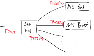
I have a PoE Ethernet Switch schematic that includes the TPS23861 and TPS23753APWR, with 1 port input and 4 port output.
Could I send it to you by email for review?
If possible, could you please share your email address?

  • Hi Brl,

    Thanks for reaching out!

    Sorry that PoE team currently are short of resource to do customer review. Please check with attached checklist for PD and I attached one PD + TPS23861 passthrough 2-ports board schematic could be similar.

    Besides, TPS23753A is only 13W input while TPS23861 in autonomous mode (No MCU to control) will not limit its port power. It means TPS23861 could have 30W x 4 = 120W output which will make TPS23753A overcurrent protection triggered 

    Let me know if you have other further questions or concerns. Thanks!

    8004.TPS2372-4+TPS23731+TPS23861 2 PSE Ports.PDF

    e2e.ti.com/.../0550.PoE-PD-Schematic-Checklist.xlsx

    Best regards,

    Diang

  • Dear Diang,

    I hope this message finds you well.

    We have a system consisting of two custom-designed PCBs:

    1. Ethernet Switch Board (Board 1):

      • Includes TPS23753A and TPS23861

      • Features 1 PoE input port and 4 PoE output ports

    2. Master Board (Board 2):

      • Includes TPS23753A

      • Features 1 PoE input port

    The 4 output ports of the Ethernet switch board are connected to the input ports of four master boards. Our goal is to use the PoE output from the switch board to supply power to the master boards via Ethernet.


    Warning️ Potential Power Issues

    We are concerned there may be a power mismatch or overload issue, due to the following:

    • TPS23753A is a Type 1 PD controller, supporting up to 13W input.

    • TPS23861, when operating in autonomous mode, does not limit port output power and can deliver up to 30W per port (total of 120W across 4 ports).

    • This mismatch could potentially trigger the overcurrent protection of the TPS23753A on the master boards.


    White check mark Questions and Clarification Needed

    1. Is it safe to use TPS23753A on both ends in this configuration?

    2. Do we need to limit the output power of each TPS23861 port to 13W to match the TPS23753A PD input?

    3. Would you recommend using TPS2372 / TPS2373 or a Type 2 PD controller on the master boards instead?

    4. Are there additional design considerations we should keep in mind to avoid protection shutdown or power integrity issues?

    We would appreciate any guidance or reference material you can share regarding proper implementation in this kind of pass-through PoE system.

    Looking forward to your expert advice.

    Best regards.

  • Hi Brl,

    Thanks for the reply! We will look into your question and get back in 5 business days. Thanks for your patience!

    Best regards,

    Diang

  • Hi Brl,

    Thanks for your patience. 

    If I understand correctly, your PSE load will be 4 x TPS23753A Type-1 PD, which could be up to 15.4W x 4 = 61.6W. This power demand may need a Class 7,8 PD. So I would recommend you to use TPS2372-4 as the switch board PoE input. TPS2372-4 can be 71.3W rated power. 

    For the TPS23861, if it will only handshake with your Class 0-3 Master boards, you do not need set power limit on TPS23861. If you want your switch board working with all standard PD Class 0-4, you will need a MCU to disable the TPS23861's 2nd classification (below links for details) 

    e2e.ti.com/.../faq-tps23861-how-to-configure-to-output-type1-power-even-if-a-type-2-pd-is-connected

    Best regards,

    Diang

  • Hi Diang,

    Thank you for your detailed response.

    On the PoE side, each of my master boards (with TPS23753A input) draws approximately 2W of power. The Ethernet switch board (with TPS23861) will have 4 outputs, each connected to a separate master board. Therefore, I don't expect any power-related issues in this setup.

    Also, please note that there is no MCU on the Ethernet switch board.

    What do you think about this configuration?

    Best regards,
    Brl

  • Hi Brl,

    I see. So your PSE will only need to work with your PDs. 

    If your Ethernet Switch Board does not need a load, you can consider TPS2378 as PD for Ethernet Switch Board. TPS2378 is Type-2 25.5W PD and does not have the DC/DC controller. If need a load, TPS23753A (13W) or TPS23731 (25.5W) could be considered.

    TPS23861 can work without MCU. 

    Master board can be TPS23753A based PD with Class-1.

    Best regards,

    Diang