This thread has been locked.

If you have a related question, please click the "Ask a related question" button in the top right corner. The newly created question will be automatically linked to this question.

BQ27427: Initialization code based on STM32

Part Number: BQ27427

Tool/software:

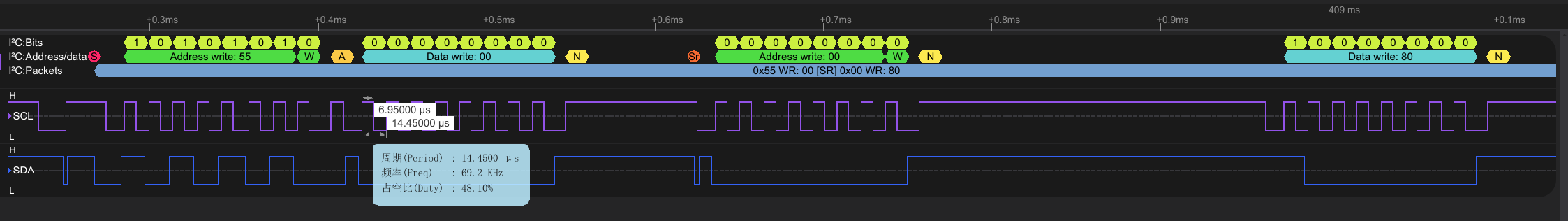
I'm trying to use software-based I2C emulation to communicate with a bq27427 fuel gauge, including initial parameter configuration and reading the remaining battery percentage (SOC), but I haven't been able to successfully read the data. When continuously reading register 0x1C and displaying its lower 8 bits, the value alternates between 0 and 255. Could you provide some reference code for this? I'd really appreciate it.

  • Hello,

    I can provide this document that goes over gauge communication: https://www.ti.com/lit/an/slua801/slua801.pdf

    Regards,

    Adrian

  • Thank you very much for your help. I observed the I2C waveform using a logic analyzer and found that the slave address (0x55) responds correctly, but the register addresses (e.g., 0x00, 0x1C) do not get acknowledged, resulting in a NACK. This prevents successful reading or writing. I'd like to ask, assuming there are no hardware issues, what could be the potential reasons for this? (Attached are the read/write program and logic analyzer screenshots. SDA is configured in open-drain mode, and SCL is configured in push-pull mode.)

    #define BQ27427_ADDR_W                0xAA
    #define BQ27427_ADDR_R                 0xAB
    #define CMD_CONTROL                     0x00
    #define CMD_STATE_OF_CHARGE   0x1C

    void BQ27427_SendControl(uint16_t cmd) {
    I2C_Start();
    I2C_Write(BQ27427_ADDR_W);
    I2C_Wait_Ack();
    I2C_Write(CMD_CONTROL);
    I2C_Wait_Ack();
    I2C_Write(cmd & 0xFF);
    I2C_Wait_Ack();
    I2C_Write((cmd >> 8) & 0xFF);
    I2C_Wait_Ack();
    I2C_Stop();
    }

    uint8_t BQ27427_Read(uint8_t reg) {
    uint8_t receive=0;

    I2C_Start();
    I2C_Write(BQ27427_ADDR_W);
    receive=I2C_Wait_Ack();
    I2C_Write(reg);
    receive=I2C_Wait_Ack();
    I2C_Start();
    I2C_Write(BQ27427_ADDR_R);
    receive=I2C_Wait_Ack();
    receive=I2C_Read(0);
    I2C_Stop();
    return receive;
    }


    void BQ27427_Send(uint8_t reg, uint8_t cmd) {
    I2C_Start();
    I2C_Write(BQ27427_ADDR_W);
    I2C_Wait_Ack();
    I2C_Write(reg);
    I2C_Wait_Ack();
    I2C_Write(cmd);
    I2C_Wait_Ack();
    I2C_Stop();
    }

    uint16_t BQ27427_Read16(uint8_t reg) {

    uint16_t s=0;
    I2C_Start();
    I2C_Write(BQ27427_ADDR_W);
    s=I2C_Wait_Ack();
    I2C_Write(reg);
    s=I2C_Wait_Ack();
    I2C_Start();
    I2C_Write(BQ27427_ADDR_R);
    s=I2C_Wait_Ack();
    uint16_t low, high;
    low=I2C_Read(1);
    high= I2C_Read(0);
    s=(high<<8)|low;

    I2C_Stop();
    return s;
    }

    uint16_t BQ27427_ReadSOC(void) {

    return BQ27427_Read16(CMD_STATE_OF_CHARGE);
    }

    Another question I'd like to confirm with you: I see in the datasheet that the VDD pin of the BQ27427 is described as a PO port. So, does the VDD pin still need to be connected to the board's VDD or VCC? If the BAT pin is connected to the battery but VDD is not connected to the board's VCC or VDD, can this chip still function properly?

  • Hello,

    There should be a capacitor connected from VDD to ground of at least 4.7uF. If this capacitor is not there then the device may not function properly.

    Regards,

    Adrian

  • This capacitor is present. Currently, there is a 2.2μF capacitor between VDD and VSS. The VDD pin correctly outputs 1.8V. Both SDA and SCL have 10kΩ pull-up resistors connected to the board’s VDD. Aside from the missing 1μF capacitor required between BAT and VSS, all other components are connected according to the reference design in the datasheet – this shouldn’t be a big issue.

    What I need to understand is: Assuming no hardware problems, what could cause the register non-response?

    My current observation:
    During read/write operations:

    Both write and read addresses (0x55) are correctly recognized and acknowledged (ACK); 

    But when writing any register address (even 0x00),  I2C_wait_ack() returns NACK.(Please take a look at the I2C waveform diagram I provided above.)

    This causes random data reads (e.g., reading register 0x1C sometimes returns 255, 99, 0, etc.). Since all registers fail to respond, read values are consistently identical and invalid.

  • Hello,

    If I2C timings are following the specs in our datasheet then it is possible that the IC is defective. Do you have other ICs that you can test with?

    Regards,

    Adrian