This thread has been locked.

If you have a related question, please click the "Ask a related question" button in the top right corner. The newly created question will be automatically linked to this question.

Variable frequency design and soft start condition

Part Number: LM3478Q-Q1
Other Parts Discussed in Thread: LM3478

Tool/software:

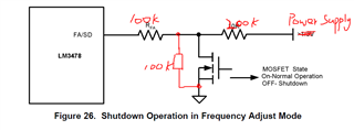
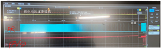
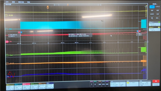
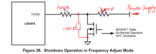
when power supply increased from 0V to 5V and MOSFET controlled as open,we found the frequency in DR pin is change,but finally DR pin will driver to high for a long time.

Question from my side:

1. Why DR pin will set as high for a long time?

2..When frequency change,are over current function and short circuit protection, control function of LM3478 still work?

3.the minimum frequency less than 100kHz during frequency change time,but shown in datasheet the minimum frequency is 100kHz?

4.for soft start function, what is the trigger condition of the this function? when the LM3478 have DR output signal at first time?

  • Hi Ni,

    Thanks for using the e2e forum.
    Here are my comments on each question.

    1. This might be related to the regulation of the output voltage. The device check the output voltage via the FB pin. If VOUT is too high, the device stop switching and waits until VOUT drops back to the target voltage. It looks like the fsw reduces, but it is actually in overvoltage protection state.
    On the other side, if the load during startup is too high, the device will try to increase the duty cycle further and further to increase VOUT up to very high duty cycles.
    Based on the waveform picture alone, I cannot say if the irregular driver signal comes from a change in VIN or Load conditions, or if the voltage at FA/SD pin changes.

    2. The switching frequency can be changed dynamically during operation by changing the RT resistance. Other functions like short circuit protection or output voltage regulation are not affected by this change. They still work, yes.

    3. It is possible to set the switching frequency setting to lower than 100kHz. However, this is not recommended, as the device has only been tested for minimum 100kHz fsw.

    4. The internal softstart will activate whenever turning on the device. The two options to turn on the device are:
    - VIN goes above the UVLO threshold (2.97V)
    - FA/SD goes below the shutdown threshold
    If both conditions are met, the device will start up in softstart mode.
    Also if you pull high FA/SD pin to enter shutdown mode and then release the pin again, the device will start up with softstart as well.

    Best regards,
    Niklas

  • Hi,Niklas,

    Many thanks for your reply.

    I add a wave picture.the dark blue 5V is the output of my power supply circuit, and which is the source of FB pin.

    you can see, there is no power build on dark blue 5V.

    So i don't think the frequency change due to output over voltage.

    do you have any other idea?

  • Hi Ni,

    Thanks for the fast feedback.
    With this information, we can rule out overvoltage, you are correct.

    The next thing to look at is the FA/SD pin signal.
    The red voltage signal seems to be gradually increasing, so I am concerned the device is entering shutdown state over and over again.
    You can see the voltage is dropping every time the device is switching, and then jumps back up when the device stops to switch.

    Can you clarify the circuit at FA/SD pin for me once more?

    Is the switch closed during operation, so you have a 100kOhm resistance between FA/SD and GND?

    Thanks and best regards,
    Niklas

  • in this wave, the KL15 is the trigger voltage of MOSFET,and which is very low,so MOSFET is OFF,  the 100kohm resistor in parallel with MOSFET

  • Hello Ni,

    Thanks for the clarification.
    I am trying to understand the two operation conditions. Please correct me if my understanding is wrong.

    If KL15 goes high, the MOSFET gets enable and the LM3478 device will operate with a fsw of ~190kHz

    If KL15 stays low, the MOSFET is disabled. FA/SD is connected to GND through the two 100kOhm resistors in series and there is the additional pull-up resistor of 200kOhm to the power supply.
    Due to the pull-up resistor, I would expect that the device stays in shutdown mode, however, the waveform shows it is turning off and on continuously even though there should a be an internal hysteresis at this pin.

    Is the intended implementation that the device stops operation if the MOSFET is open, or is it meant to operate with a lower switching frequency?
    It might be necessary to adjust the resistance of to pull-up resistance or the pull-down resistance in parallel to the MOSFET to achieve a clear shutdown and operation mode.

    Thanks and best regards,
    Niklas

  • Many thanks, we plan to do the optimization,but i want to understand the behavior of LM3478 as the wave shown.

    do you have some ideas about my first question above?

  • Hi Ni,

    You are referencing to the long DR pulse, correct?

    LM3478 controller is originally based off a Buck controller. This is the reason the datasheet say this device can support "100% duty cycle". This makes sense for a buck, where it is bypassing the input voltage, but not for a boost, where it would mean a short of the input supply.
    This means while the device says it is capable of 100% duty cycle, this is not actually the case for a physical boost design.

    Right now I cannot give a full explanation why there seems to be a on-pulse of ~100ms.
    We never had any issue with LM3478 shorting the input supply, so I would assume this behavior disappears as soon as the turn-on/turn-off circuit is stabilized.
    However, to investigate further into this behavior, would it be possible to make an additional waveform, where we see the driver signal together with the switch note voltage and the inrush current?
    I would then also loop in our design team to check into the internal design for possible root causes.

    Thanks and best regards,
    Niklas

  • Hello Niklas,Many thanks.

    Just for more clear description of the wave, this is for a fly-back circuit. and i just make the trigger voltage(KL15) of MOSFET (FA/SD pin) off. and slowly increase the Power supply(KL30), FA/SD (red one in the wave) pin voltage is between 0.6V~1.35V during this time.The green Icur is the input current of the power supply. 5V in the wave is the output of fly-back circuit. Hope these information will help your team for the root cause.

    Thanks again.

  • Hi Ni,

    Thanks a lot for the waveform description.
    It is good to know that the input current is already included.
    What confuses me with this signal is that the current jumps up to ~1A and stays stable at this value during the long driver pulse.
    Is there a current limit set with the power supply?

    Also, would it be possible to share the schematic of the LM3478 circuit and power stage?
    The more information we have, the faster we can narrow down possible root causes.

    Thanks and best regards,
    Niklas

  • Hi Niklas,

    Do you have same finding?

  • There is no current limit for the power supply

  • Hello Ni,

    Thanks for the confirmation.
    I did not have any new findings yet, as I was waiting for feedback on the current limit and the schematic.

    It is not possible to share the schematic of the application?

    Thanks and best regards,
    Niklas