LM5160-Q1: the PWM signal is stop during start-up;

Part Number: LM5160-Q1
Other Parts Discussed in Thread: LM5160, LM5160DNTFBKEVM

Tool/software:

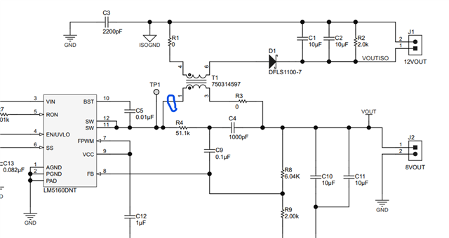
we test the LM5160 EVM board. we can find the PWM signal of chip is stop during power supply start-up; stop time is about 40us;

the peak current value of transformer primary side is about 430mA;

why dose the chip output stop?

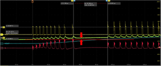
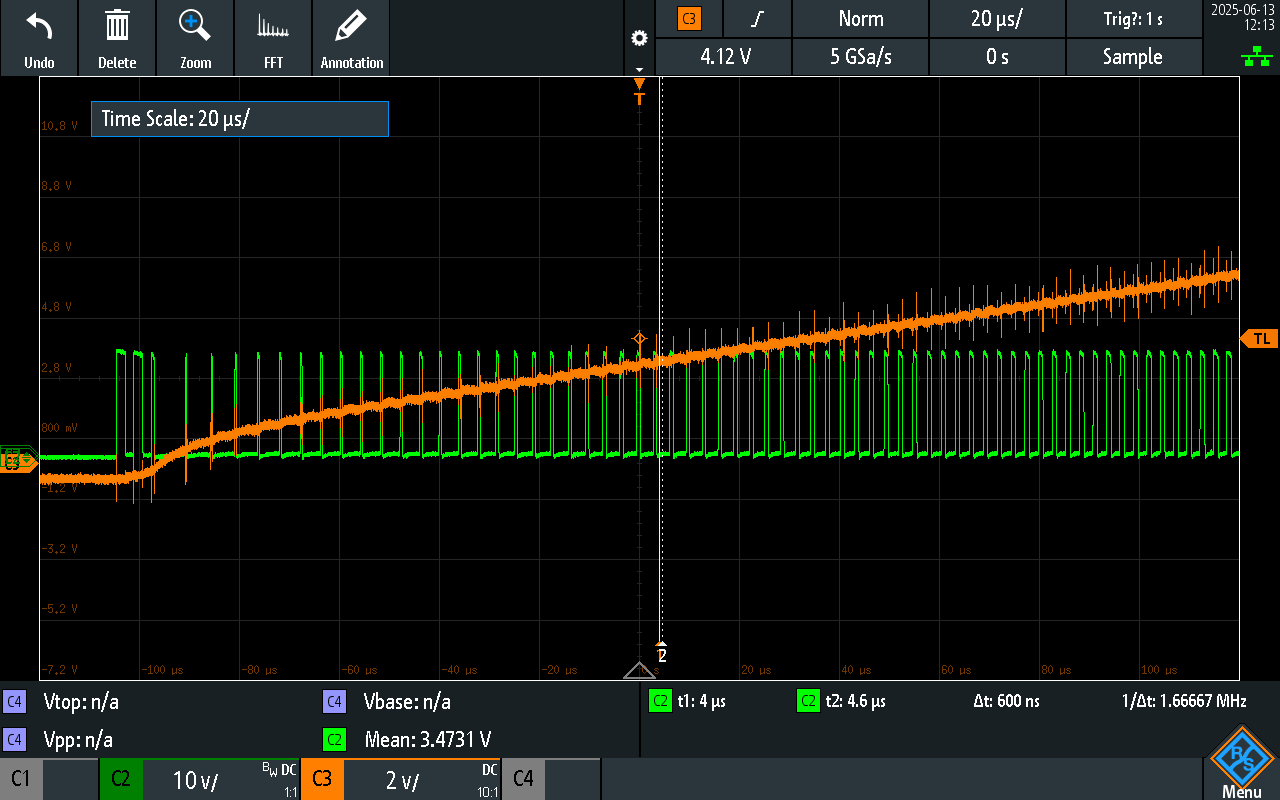
  • Yellow is PWM(sw pin);
  • Blue is output voltage;
  • Green is FB pin;
  • Red is transformer primary side current;
  • Hi Xiaobo,

    Please share the schematic to understand the circuit. 

    Also, it would be better if you can fill the excel tool LM5160DNTFBK-CALC Calculation tool | TI.com [select flybuck] with your operating conditions and share with us.

    Regards

    Arpita

  • we use the EVM board (LM5160DNTFBKEVM)for test;only change the value of  C13= 0.082uF capacitor with 2.2nF capacitor;

  • It looks like same to the below thread. Please follow the thread for more information. 

    (+) LM5160: abnormal switch off - Power management - INTERNAL forum - Power management - INTERNAL - TI E2E support forums

    i would like to recommend using resistive load and check if start-up is smoother.

  • What was the output voltage primary and secondary? was it default EVM?

    Regards

    Arpita

  • To simplify the issue, we do not discuss the user‘s own circuit schematic; TI EVM board has a same issue; Can you help test and confirm this issue? for evm board, only change the value of  C13= 0.082uF capacitor with 2.2nF capacitor;

  • Hi Xiaobo,

    Hi Xiaaobo,

    Please go through the datasheet section 7.3.7 

    The length of the off time is controlled by the FB voltage and the input voltage VIN. As an example, when VFB = 0 V and VIN = 24 V, the off time is set to 10 µs. This condition occurs if the output is shorted or during the initial phase of start-up.

    Here is the EVM test results with CSS=1.5nF.

    I had tested with Iout1=20mA, Css=1.5nF Cout being EVM default. I observed off time ~5.15us. I believe very less Tss and higher Co can cause high inrush current. 

    In your case, the off-time is ~47us. To explain this, we need to have details if there is change on the EVM schematic (if any). Also please confirm the operating conditions.

    Regards

    Arpita

  • So, you mean the current limit value when the chip starts up is different from what's listed in the datasheet(typ 2.5A)? Is this value related to the voltage of the SS pin? Is there a precise formula to calculate what this current limit value should be?

  • Hi Xiaobo,

    No, the current limit is always same as what is listed in the EVM.

    Let's understand that during start-up, there is inrush current drawn from the supply. The output capacitor requires current to charge them from their initial or zero state to their final steady state voltage. This current can have a high peak depending upon voltage slew rate and source impedance and is referred as inrush current.

    You can calculate inrush current approximately using  
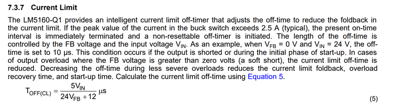
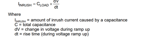
where C_LOAD=output capacitance, dv~ Vout, dt=Tss.

    Large output capacitance and very fast start-up [i.e. very less Tss as in customer case] can lead to very high inrush current resulting in undesirable operation.

    In your case, the off time is ~47us. To comment on this, we need to have details if there is change on the EVM schematic (if any).

    Hope this explains the inrush current phenomena during start-up.

    Regards

    Arpita

  • thanks Arpita;

    That's the point, I don't understand;because we used the current probe to measure the peak current (pin12&pin11 output current);it's about 0.43A, which is well lower than the limit value in datasheet (2.5A).

    yes,in my test case, the off time is 47us; so,then we use the EVM board to test with min modification. but EVM still have off time(less than 47us);

    We want to know why it have this off time,because  we also used the current probe to measure the peak current for EVM board. and don't found big current value which can go up to limit of 2.5A.

    Regards

    • I would like to recommend using resistive load and check if start-up is smoother
      • Any update on this?

      • yes,in my test case, the off time is 47us; so,then we use the EVM board to test with min modification. but EVM still have off time (less than 47us)

                It is very difficult to comment without having knowledge of Cout values and EVM modifications.

      • it's about 0.43A, which is well lower than the limit value in datasheet (2.5A).

      Where are you exactly measuring current? please confirm if you have checked between IC pin11/12 and T1 pin 1 like this. Also, can you please attach

      waveform of iL with good resolution with A/div, BW info etc for proper understanding? Sorry I cannot see iL_peak level due to poor resolution.

    • 1)yes, we use resistive load; for EVM test, only change value of the C13 from 0.082uF to 2.2nF;

      2) yes, it's difficult to comment the customer board; you can focus on EVM board test;

      3)We only want to know why  the chip have some cycle of off time  during the startup;(even the EVM also have this issue)

      4) yes, the measurement condition is same with the picture above;

      5)for waveforms, which you can test reproduce on an EVM board;

    • Hi Xiaobo,

      As I have explained, the EVM behavior is not an issue and looks expected to me.

      Please go through the datasheet section 7.3.7 

      The length of the off time is controlled by the FB voltage and the input voltage VIN. As an example, when VFB = 0 V and VIN = 24 V, the off time is set to 10 µs. This condition occurs if the output is shorted or during the initial phase of start-up.

      Also, any update on below?

      • waveform of iL with good resolution with A/div, BW info etc for proper understanding? Sorry I cannot see iL_peak level due to poor resolution.
      • Kindly share the results with resistive load in default EVM.

      Regards

      Arpita

    • Thanks for your patient explanation!

      1)but we don't find the condition of when VFB = 0 Vand VIN = 24 V,  for both my board and TI EVM board;(The red arrow is shown in the image);

      this is why i don't understand this issue;

      don't  have VFB = 0 and don't exceed the limit of 2.5A; why does EVM have about 10us off time ?

      2) for waveform of iL with good resolution with A/div, BW info etc;This may be due to the website, my image became blurred after uploading.

    • Hi Xiaobo,

      It looks like inrush current would be much higher than 0.43A for the Css=2nF. As from the shared waveforms current values cannot be read, would advise to reattach the waveforms to confirm that the current amplitude is ~0.43A.

      Also, for further debugging, please share the start-up behavior with resistive load in EVM as suggested earlier.

      Regards

      Arpita

    • Hi Xiaobo,

      Did you check with a resistive load start-up? Does it resolve the issue?

      Regards

      Xiaobo

    • hi Arpita,

      not resolve the issue yet

    • Did you check with resistive load? Can you please share the waveforms with pure resistive load vs e load? Sometimes the electronic load in CC mode while start-up can cause the issue.

      Regards

      Arpita

    • hi Arpita;

      we had not do any test with  electronic load ;

      I mentioned it about,for EVM test, only change value of the C13 from 0.082uF to 2.2nF; no change for other parts;

      it still have some cycle of off time.

    • Hi Xiaobo,

      I have understood that you used EVM but what was connected to the EVM load terminals? Could you please confirm?

      Regards

      Arpita

    • Hi Xiaobo, 

      please update once you have tested with purely resistive load with EVM. Please re-open the thread once you have above requested waveforms

      regards

      Arpita