BQ25750: The question about the BQ25750 power path switch

Part Number: BQ25750

Tool/software:

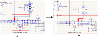
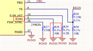
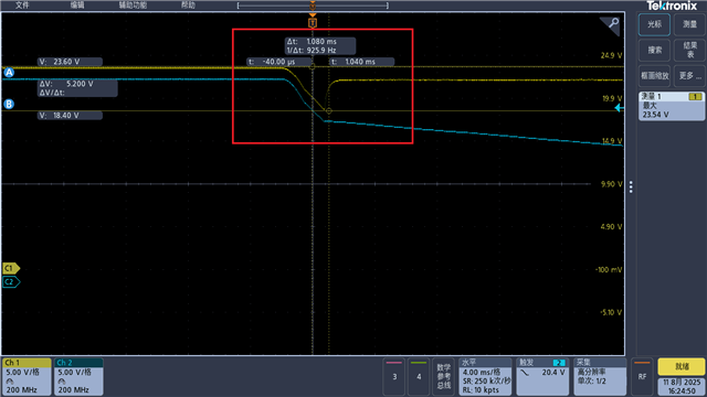
Hello, when I was using the BQ25750, the path could not be switched under load conditions. I found the relevant solution from the previous forum, which stated that the BATFET should be connected to the SRP side of the resistor. When used in this way, the path switching is fine. However, the charging current is different from the set value. When the setting is 1A, it is only around 500mA. What should I do in this situation? Can the resistor be removed directly? Or are there any other solutions?

  • Hello Jianbo,

    Thanks for working on this. I have a few questions to help debug this:

    • Can you send me a block diagram / picture of how the BATFETs are connected to the BQ25750?
    • What's the input voltage, output voltage, and system load current?
    • Are you using the ICHG resistor or the register to set the ICHG current?

    You've probably already seen this, but here's a link to the power path FAQ for reference.

    Best Regards.
    Ethan Galloway

  • Hi Ethan,

    These are some scenarios and conditions about my system operates.

    1. This picture shows the changes in the connection of BATFETS to the BQ25750 resistor in the system.(From A to B)


    2. The input voltage is 24V DC. My battery voltage usually ranges from 18V to 25.2V. During the test, I used an electronic load with a load capacity of 2A.(In reality, the maximum current will not exceed 2.5A)

    3. I used the register to set the ICHG current.

    Looking forward to your reply.

    Thank you.

  • Hello Jianbo,

    Thanks for the new information.

    I think the ICHG pin might be getting noise on the pin. Can you install an RC filter in parallel with the ICHG resistor? We recommend this the ICHG resistor is greater than 5kΩ.

    To diagnose this, can you set ICHG_REG = 2A and EN_ICHG_PIN=0 in the registers? This will disable the ICHG pin. If the IC outputs the correct current, that means the ICHG pin is the root cause of the behavior.

    Best Regards,
    Ethan Galloway

  • Hi Ethan,

    What a great news! The system is running very successfully.

    And, I still have some other questions. 

    1. When my BATFETS bypasses the SRP of RBAT_SNS and directly connect  SRN, will RBAT_SNS still be effective?  What other functions does RBAT_SNS have?

    2. If RBAT_SNS has no other functions, can this resistor be removed and the SRP and SRN be directly connected instead?

    3. Are there any other points that need attention in this system?

    Looking forward to your reply.

    Grinning

  • Hello Jianbo,

    Thanks for being patient with this. We are busy at the moment and we will get back to your question later this week.

    Best Regards,
    Ethan Galloway

  • Hello Jianbo,

    That's great to hear!

    1. When my BATFETS bypasses the SRP of RBAT_SNS and directly connect  SRN, will RBAT_SNS still be effective?  What other functions does RBAT_SNS have?

    RBAT_SNS will still be used to regulate the battery charging current.

    2. If RBAT_SNS has no other functions, can this resistor be removed and the SRP and SRN be directly connected instead?

    The system will still need RBAT_SNS.

    3. Are there any other points that need attention in this system?

    There's none that I can think for your circuit at the moment. Let us know if you have any other questions.

    Best Regards,
    Ethan Galloway

  • Thanks!!!!Grin

    Sorry for the long reply.

    The system is currently running normally.Clap

  • Hello Jianbo,

    No problem. I'm glad your system is working!

    Let us know if you have any other questions.

    Best Regards,
    Ethan Galloway

  • Hello Ethan,

    Sorry, during the testing process of the routing system, the path switching failed.

    We conducted the test using an oscilloscope.

    When the power supply is cut off, the power is switched from the main power source to the battery. There will be a drop in voltage, as shown in the red box in the figure (yellow line).

    Is there any way to optimize this phenomenon? So that the circuit can switch more smoothly, similar to a downward slope.

    Is this phenomenon related to the parameter Vvacuvp that we have set?

  • Hello Jianbo,

    Thanks for being patient with this. I'll get to your question tomorrow.

    Best Regards,
    Ethan Galloway

  • Hello Jianbo,

    Thanks for working on this.

    Is this phenomenon related to the parameter Vvacuvp that we have set?

    Setting the ACUV voltage a bit higher may help.

    Is there any way to optimize this phenomenon?

    I have a few suggestions:

    • If the IC is only going to be in buck-only mode, you might be able to use a single FET and use ideal diode mode
    • Can you use auto reverse mode? Auto reverse mode has a faster response time than the battery FETs. Once the voltage stabilizes, you can go back to turning on the BATFETs.

    Let me know if these will work for your system.

    Best Regards,
    Ethan Galloway

  • Hello Ethan,

    emmm...When I set a higher ACUV value, the charging voltage must be increased accordingly. Otherwise, charging will not be possible. Is this correct?

    During the testing process, when I changed the ACUV setting from 20V to 22V, charging could only occur when the input voltage was greater than 24.5V. At this point, the system has been operating for more than 24 hours without being disconnected.

    When I further reduced the ACUV voltage from 22V to around 20.6V, charging was possible with an input of 24V, but the system would cut off the power supply within 24 hours.

    1.The external input voltage for our equipment is 24V, and the battery is composed of 6 strings(19.2V~25.2V). Not only does it operate in the buck mode. 

    2. We hope that it can automatically switch to battery power supply without the need for software control when the external power source is removed. May I ask for any suggestions?

  • Hello Jianbo,

    emmm...When I set a higher ACUV value, the charging voltage must be increased accordingly. Otherwise, charging will not be possible. Is this correct?

    During the testing process, when I changed the ACUV setting from 20V to 22V, charging could only occur when the input voltage was greater than 24.5V. At this point, the system has been operating for more than 24 hours without being disconnected.

    You should not have to increase the charge voltage to get the device to starting.

    Can you provide a register dump when this behavior is occuring?

    Best Regards,

    Christian.

  • Sorry, currently we do not have software involved in this project.

    The existing parameters are basically the default ones.

    It is all controlled by the hardware.

  • Hello Jianbo,

    Thank you for the clarification, Please allow me time to look in to other possible solution.

    Best Regards,

    Christian.

  • Hello Jianbo,

    emmm...When I set a higher ACUV value, the charging voltage must be increased accordingly. Otherwise, charging will not be possible. Is this correct?

    It sounds like the BQ25750 is in VAC_DPM? Can you measure the voltage on the ACUV pin? The pin will be near 1.21V if the BQ25750 is in VAC_DPM.

    Also, do you know what the charge current is while the IC is in this mode?

    We have an FAQ on ACUV and ACOV that goes into more detail on this.

    Best Regards,
    Ethan Galloway