This thread has been locked.

If you have a related question, please click the "Ask a related question" button in the top right corner. The newly created question will be automatically linked to this question.

LMG1210: LMG1210

Part Number: LMG1210

Tool/software:

Dear Team,

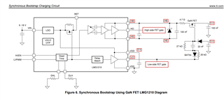
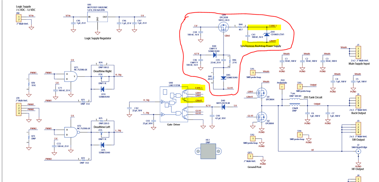
I am currently working on a design where I am using LMG1210 gate driver. I have gone through the application report SLUA931 for LMG1210 (synchronous bootstrap). I would like know the design calculations for the Synchronous Bootstrap Using GaN FET, mentioned in page number 5,6.

Referring to the attached diagram, please let me know how the resistors, capacitors, diodes are designed for the Synchronous Bootstrap.

  • Hello,

    This circuit is taken from the EPC9066 design https://epc-co.com/epc/Portals/0/epc/documents/schematics/EPC9066_Schematic.pdf

    The Schematic you attached has a typo. The 20k resistor in parallel with the BAT54 diode should be 20 ohms. 

    When the LO pin is HI, the gate of the sync bootstrap fet gets charged through R45.

    C45 pushes the gate to 5V above the 5V rail) When LO goes low, the gate is rapidly pulled back to 5V (0 VGS on the bootstrap device) through diode D45. So the bootstrap FET turns on when LO is on and turns off when LO is off

    There is a much faster charging of the bootstrap cap when the low-side is on because it is charged through a turned-on FET instead of through a diode.

    There is also no Qrr since GAN have no minority carriers involved in "diode" reverse conduction.

    R44, C41, and D41 is a simple shunt voltage regulator circuit to regulate the HB voltage.

    C45, R46 and R45 set the turn on and turn off time of the bootstrap FET. The values need to be balanced so that the bootstrap switch is not turned on too quickly but turned off as fast as possible. This is to prevent overcharge due to negative HS voltage or the GaN FET being on during deadtimes.

    Best,

    Walter

  • Hi Walter,

    Could you please share the constraints or considerations for selecting the diodes D41, D44, and D45? I’m currently using the LMG1210 gate driver along with the GS66508B GaN FET in a full-bridge topology. The system is designed with a maximum drain supply voltage of 200V.

    I would like to understand how to properly select these diodes — specifically, the required breakdown voltage, forward voltage drop, and current rating.

    Regards,

    Athira K Vinod

  • Hello Athira,

    D41 can be most 5.1V breakdown zener diodes with sufficient current handling for the shunt circuit. The highlighted part is the one used in the example.

    D44 and D45 can be a fast small signal schottky diode 30-40V, 200-600mA. ~300mV forward voltage drop.

    Thanks,

    Walter