This thread has been locked.

If you have a related question, please click the "Ask a related question" button in the top right corner. The newly created question will be automatically linked to this question.

LM5148: investigation

Part Number: LM5148
Other Parts Discussed in Thread: LM25145

Tool/software:

Hi,

I am looking for a device that can operate under the following conditions.

I tried to check the operation using LM5148, but subharmonic oscillation occurred.

Changing the switching frequency or inductor would improve the situation, but that would not meet our usage requirements.

Please recommend a device.

-----

Device: Control IC (not built-in FET)

Control: analog (not serial interface)

Type: Buck or buck-boost

Input voltage: 22.8Vmin, 24.0Vtyp, 25.2Vmax

Output voltage: 21.5V

Output current: 8.1Amax

Soft start: Variable

Output capacitor: 4000uF

Switching frequency: 200-300kHz

Inductor: 3.3-4.7uH

Mode: FPWM only, or selectable PFM and FPWM (oscillation between 130-160kHz is not acceptable)

Other: Subharmonic oscillation must not occur

-----

Best regards,

  • Hi,

    I am a little confused on your requirements:

    Vin Range: 22.8V to 25.2 V

    Vout: 21.5V

    Iout: 8.1A

    • Regarding the Cout - Is 4000uH a mandatory requirement here? 
    • Why is external FET mandatory? 
    • Is the switching frequency between 200-300kHz mandatory or you are flexible? 

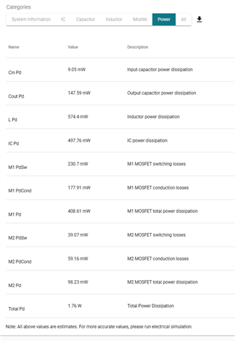
    Meanwhile, you can look at https://webench.ti.com/appinfo/webench/scripts/SDP.cgi?ID=9D7A4605363CC867

    Thanks,

    Best Regards,

    Taru

  • Hi,

    [Cout=4000uH] This is the input capacitor of the output device. The DCDC is required to start up normally even with a large-capacity capacitor.

    [not built-in FET] [200-300kHz] This is to suppress the temperature of the components.

    Not only the junction temperature of the semiconductor, but also the solder temperature must be kept below our standard value.

    I think that the standard can only be met with external FETs and a low switching frequency.

    Thank you for the Webench address. I'll take a look.

    If you have any recommended devices, please let me know.

    Best Regards,

  • Hi User, 

    [Cout=4000uH] This is the input capacitor of the output device. The DCDC is required to start up normally even with a large-capacity capacitor.

    When powering high capacitive load - a longer soft start can help the DC/DC increase the voltage in a controlled manner. The LM25145 does have an external SS - so you can have a longer soft start and have a controlled current and voltage rise in your system. You can also have an inductor/eFuse after the DC/DC stage to further help prevent current surge on your rail. 

    Will the 4mF capacitive load undergo multiple sudden charge/discharge cycles or does it just requires a controlled voltage rise during start-up?

    Thanks,

    Best Regards,

    Taru

  • Hi,

    There may be load fluctuations, but I don't have the actual product yet so I don't know to what extent. First I want to choose one that can start up normally.

    The LM25145 has a variable soft start, so it seems like it can start up even with Cout=4000uF.

    However, like the LM5148, it is peak current mode control, and the same slope compensation explanation is written. When I used the LM5148 under the aforementioned conditions (Vin=24V, Vout=21.5V, fsw=300kHz, L=3.3uH), subharmonic oscillation occurred, so I think the LM25145 will also oscillate.

    Best Regards,

  • Hi User,

    Can you share where you simulated and got subharmonic oscillations? Sub harmonic oscillations because of improper slope compensation - which can be avoided if the device and the design are designed well. 

    Furthermore, subharmonic oscillations is a property of current mode control scheme. LM25145 is a voltage mode control device which doesn't have subharmonic oscillation. 

    Thanks,

    Best Regards,

    Taru

  • Hi,

    The reason why subharmonic oscillation occurred in the actual measurement of LM5148 was because the inductance was smaller than the recommended value. This can be improved by increasing the inductance or increasing the switching frequency, but the component temperature will not meet our criteria.

    -----

    I was looking at a different datasheet. As you say, the LM25145 is a voltage mode control device.The LM25145 seems to meet the usage requirements.

    Please tell me about the LM25145.

    -If the component temperature is too high with one LM25145, I would like to generate one 21.5V output using two LM25145s. Is interleaved operation possible?

    -Are there any newer generation or alternative products similar to the LM25145?

    Best Regards,

  • Please tell me about the LM25145.

    Please go through the datasheet of the device here: https://www.ti.com/lit/gpn/lm25145

    -If the component temperature is too high with one LM25145, I would like to generate one 21.5V output using two LM25145s. Is interleaved operation possible?

    I dont think there will be thermal issues here. Please see the WEBENCH design that I shared earlier

    and use the design calculator of this device to get an idea of the kind of power dissipation expected.

    And to answer your question completely - yes, the LM25145 does support interleaved operation. You will find the details in the datasheet. 

    -Are there any newer generation or alternative products similar to the LM25145?

    LM25145 is part of the newest generation of voltage mode buck controller family from our portfolio. 

    Thanks,

    Best Regards,

    Taru

  • Hi,

    Thanks. I'll consider the LM25145 as a device that meets my requirements.

    Best Regards,