


Other Parts Discussed in Thread: LM7480
Tool/software:
Hello teams
We use the LM7480 to protect against overvoltage, overcurrent, and load dump, and we have confirmed that it is functioning properly.
With the following circuit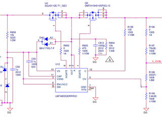
We have found one problem with measuring waveforms.
The absolute maximum ratings of the device are specified as -0.3V to 15V between DGATE and A terminals as shown below.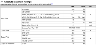
The waveforms that we tested against JASO D001 standards (which are similar to ISO 16750-2 and ISO 7637-2 standards) are shown below.
There is an undershoot of about 10 ns between the DGATE and A terminal at a moment below -0.3 V.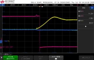
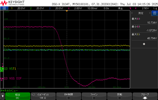
CH1:Yellow:Power input
CH2:Green:Q3 FET source(A pin)
CH3:Blue:Q3 Drain
CH4:Red:Q3 Vgs
The right-hand windows, from top to bottom: VGS maximum , VGS minimum , Power input maximum.
Since this is being measured with a high voltage differential probe, it is possible that the capacitance or inductance of the probe is affecting the measurement.
1.What negative effects could this phenomenon possibly have on the device?
2.What are possible solutions to this problem?
